")
If it's producing audio with the jumpers, everything on the main board is probably OK.
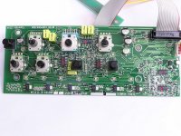
It's possible that all of the op-amps on the preamp board need to be replaced. Plug the preamp board in and see if any of the op-amps are running hotter than the others. Change the ones that are running hotter than the others first. If none are running hot, find the ones that have significantly different voltage between the two input pins for each of the 4 op-amps on each IC. I think the 3 amongst the pots and switches are used for audio. I think the other two near the corner of the board are for the display (but I'm not sure).
Look up the datasheet for a TL074. It will give you the pin configuration.
Mouser:
595-TL074CD
You have to be careful when ordering SMD ICs. There's an SOP and an SOIC. I've seen both designated as SO from time to time. The SOP is wider and won't generally fit on the pads. The SOIC package is the most commonly used package for op-amps.
Have you checked to see if any had too much offset between inputs or if there were any running hot?
Well, i replaced the op-amps, still no go. I get better numbers than before but on 3 of them im not getting +VCC
Op-amp#1
Pin 1: -10.8
Pin 2: -10.74
Pin 3: 1.01
Pin 4: -11.28 **
Pin 5: 2.51
Pin 6: -10.68
Pin 7: -10.89
Pin 8: -10.81
Pin 9: -10.65
Pin 10: 3.87
Pin 11: -15.01
Pin 12: -10.64
Pin 13: 2.88
Pin 14: -13.69
Op-amp#2
Pin 1: -10.76
Pin 2: -10.62
Pin 3: 3.69
Pin 4: -11.21 **
Pin 5: -0.001
Pin 6: -0.125
Pin 7: -10.33
Pin 8: -10.27
Pin 9: -0.128
Pin 10: -0.001
Pin 11: -15.02
Pin 12: -0.002
Pin 13: -0.148
Pin 14: -10.38
Op-amp#3
Pin 1: 0.001
Pin 2: -0.001
Pin 3: -0.002
Pin 4: 16.00
Pin 5: -0.001
Pin 6: -0.003
Pin 7: -0.003
Pin 8: -0.003
Pin 9: -0.001
Pin 10: -0.001
Pin 11: -15.18
Pin 12: -0.002
Pin 13: -0.001
Pin 14: -0.001
Op-amp#4
Pin 1: -13.61
Pin 2: -11.86
Pin 3: -13.16
Pin 4: 15.9
Pin 5: -13.59
Pin 6: -4.08
Pin 7: 4.80
Pin 8: 9.07
Pin 9: 0
Pin 10: -0.001
Pin 11: -15.05
Pin 12: -0.002
Pin 13: -0.002
Pin 14: 0
Op-amp#5
Pin 1: -13.12
Pin 2: -13.11
Pin 3: -10.6
Pin 4: -13.88 **
Pin 5: -6.54
Pin 6: -13.11
Pin 7: -13.15
Pin 8: -13.20
Pin 9: -13.20
Pin 10: -0.001
Pin 11: -15.22
Pin 12: -6.53
Pin 13: -11.69
Pin 14: -13.18
Attachments
I can't tell you what caused it but I think you should add some sort of protection to the circuit to shut down the amp if the voltage goes above ~18v.
You've already been through this once so you may not need help getting it repaired. Before you reinstall it, let me know and we'll do something that will help protect the amp.
You've already been through this once so you may not need help getting it repaired. Before you reinstall it, let me know and we'll do something that will help protect the amp.
There are many ways to do it. The simplest would be to insert a fuse (2 amp?) in series with the regulator transistor. Then you could parallel an 18v 5w Zener across its outputs. If the transistor shorts and the voltage goes above 18v, the fuse will blow. This should protect most of the components on the 15v rail.
I wouldn't cut the trace. Place heatshrink on the transistor leg (so it can't short to the clamp) and bend it so it extends from under the clamp. Solder one end of the fuse to the transistor's leg. The other end of the fuse will go into the through-hole.
After you get it working (including having the fuse in the circuit), use a non-conductive probe and push on various areas of the board to see if you can find any intermittent problems that are causing this to happen. At first, do it with the preamp board out of the circuit. If you don't find any problems with the preamp board out, reconnect it and try to find an intermittent problem with it in the circuit. Look closely at the board (with a lighted magnifying glass) to see if you can find anything that looks like it could be a problem. Sometimes a small ball of solder in just the wrong place can cause problem.
After you get it working (including having the fuse in the circuit), use a non-conductive probe and push on various areas of the board to see if you can find any intermittent problems that are causing this to happen. At first, do it with the preamp board out of the circuit. If you don't find any problems with the preamp board out, reconnect it and try to find an intermittent problem with it in the circuit. Look closely at the board (with a lighted magnifying glass) to see if you can find anything that looks like it could be a problem. Sometimes a small ball of solder in just the wrong place can cause problem.
- Status
- This old topic is closed. If you want to reopen this topic, contact a moderator using the "Report Post" button.
- Home
- General Interest
- Car Audio
- MTX TA7801 repair