Everything on the board is running about 80 degrees, except the +/- 15V regulators are 105 degrees, and the servo opamp jumped to 160 degrees within 30 seconds.
The amp runs perfectly fine when testing, other than drawing a heuge amount of amperage for the output, my 12Amp power supply and car battery can barely keep up with it at a moderate listening volume for more than 2 minutes, I have run equally as large amps as this with no issues.
The amp runs perfectly fine when testing, other than drawing a heuge amount of amperage for the output, my 12Amp power supply and car battery can barely keep up with it at a moderate listening volume for more than 2 minutes, I have run equally as large amps as this with no issues.
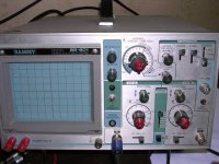
Well, I am having one heck of a time trying to use this scope, I am used to the fancy multi thousand dollar scopes at school, but this thing has me lost, I really wish they would have taught us how to use them. I can't get it to show a solid waveform. I calibrated the v/div, but had nothing to calibrate the sec/div.
Having said that, all the wave forms that I can kinda get to show up look very close, except pin 2 of the servo op-amp, it has ~1Vp-p noise.
Just in case your experienced with this scope, it's a Ramsey BS-601.
Having said that, all the wave forms that I can kinda get to show up look very close, except pin 2 of the servo op-amp, it has ~1Vp-p noise.
Just in case your experienced with this scope, it's a Ramsey BS-601.
It was 1v of noise riding on the solid line (constant DC). I haven't removed any other components around the opamps other than the opamps themselves many times, and replacing the opto couplers and R421.
I am attaching a pic of the Scope, I have been playing with it for the last hour with no real luck.
I am attaching a pic of the Scope, I have been playing with it for the last hour with no real luck.
Attachments
The trigger source needs to be internal. Try the sync in all positions. Pull the trigger knob and adjust to lock the signal.
That's a normal (to small) scope. The school must have LCD scopes if you consider this large.
If the signal on pin 5 (of the same IC) is correct, this one must be correct. This one feeds pin 5.
That's a normal (to small) scope. The school must have LCD scopes if you consider this large.
If the signal on pin 5 (of the same IC) is correct, this one must be correct. This one feeds pin 5.
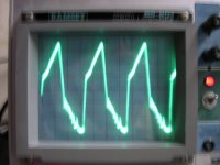
Ok, I got the scope figured out. Input one seems to be fried. I played around with input 2 and I am getting great signals now. All the waveforms are identical to the ones in your pictures except pin1 of the servo opamp isn't as uniform of a triangle wave as yours was. I am including a picture.
Attachments
If it still got hot with that resistor out of the circuit, it may be defective. I don't know anything that could make it run hot if the regulated input voltage is not excessive and it has no external load. Removing R417 should have remove the load from pin 7 and pin 1 only drives pin 5 (if I'm not mistaken) which is an insignificant load.
Is the other 5532 also running at 105°F?
Is the other 5532 also running at 105°F?
- Status
- This old topic is closed. If you want to reopen this topic, contact a moderator using the "Report Post" button.
- Home
- General Interest
- Car Audio
- MTX TA7801 repair