Most of the circuits here are some kind of transimpedans circuits, get the current in, mirror it over, I-V convert it RIAA shape, buffer it and take it out, so many options so many designs.
Great now can we have balanced one please

(PS FDW Everything be alright tomorow
Last edited:
PLs look at post 8428
http://www.diyaudio.com/forums/analogue-source/154210-mpp-843.html#post3408743
http://www.diyaudio.com/forums/analogue-source/154210-mpp-843.html#post3408743
The balanced input is working !
Gain is a little low so i think i can reduce the emitter resistors to 5 Ohm.
I will tell you more soon but i already measurewd frequency response and it goes to 7MHz.
I had to ground the negative side for this because my generator and scope share the same ground. The 100kHz square looks clean, no overshot.
I will measure the offset and check noise but what i hear sounds good.
Why a guy that starts with an S said that this circuit brings trouble i do not now.
I just works fine.
Or this post..


tanks for link
now one need very clever ones to turn that in 2 proper drawing whit possibly PCB to boot so one can weld same whatnots and nagh about WTF is not working even whit black (preferebly) whatnots wrong way round
Some picture taken last Sunday afternoon at Waldeck in Germany
Thanks FdW......great to see Joachim looking very fit!
OK--- just don't expect too much Help.... As No time is what i have plenty off.
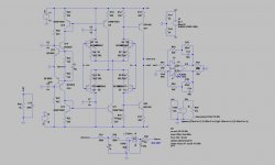
The circuit here is balanced input, collected to single node out, and than through the nice sounding balanced driver, The Riaa is split, which all my last circuits had been. The treble cut is in the first section- increasing overload margion on the second stage.
I placed a servo in the first stage, This is not so much for the DC, but to alter the working points of the lower and upper section to a place where they have the same gain, Shifting the curve to match.(so to speak)
Its advisable to find good quads/or two matched doubles for the NPN-PNP input transistors. The BD139/140 should be HFE matched.
For the opamp I would advise to consult the Datasheet, as there is a good circuit for nulling the opamp offset.
Attachments
Last edited:
OK--- just don't expect too much Help.... As No time is what i have plenty off.
Tanks will have a good look at it
Spit RIAA yes agree love it myself
If you (all) want to know why I am so silent? I need to build 2 stereo amplifier for the High-End 2015 in Munchen, please come and listen to them
The amps will play here (other side from the road at the main exhibition place)
Zenith - Die Kulturhalle
Lilienthalallee 29
80939 München
Germany
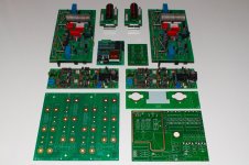
The picture contains:
One full set of boards for one stereo unit
Sorry not all boards available fully stuffed
Left from main capacitor bank
Right front power rectifiers and house keeping
Behind that panel meter mounting board (and lights)
Then 2 pcs of pre-amplifier (same as line stage)
Left/right back, 2 power amps
In-between, left on/off- softstart- and muting- circuit (stuffed)
In-between, right, LED-control board
Center back, 2 x loudspeaker zobel and common-mode filter
The amps will play here (other side from the road at the main exhibition place)
Zenith - Die Kulturhalle
Lilienthalallee 29
80939 München
Germany
The picture contains:
One full set of boards for one stereo unit
Sorry not all boards available fully stuffed
Left from main capacitor bank
Right front power rectifiers and house keeping
Behind that panel meter mounting board (and lights)
Then 2 pcs of pre-amplifier (same as line stage)
Left/right back, 2 power amps
In-between, left on/off- softstart- and muting- circuit (stuffed)
In-between, right, LED-control board
Center back, 2 x loudspeaker zobel and common-mode filter
Attachments
If you (all) want to know why I am so silent? I need to build 2 stereo amplifier for the High-End 2015 in Munchen, please come and listen to them
This is really interesting, but:
Sorry, but probably I missed something?The thing is, here we talk about Joachim's circuits (and related (even remotely)) not Marantz. So where is the reference to any of Joachim's circuits?
If you (all) want to know why I am so silent? I need to build 2 stereo amplifier for the High-End 2015 in Munchen, please come and listen to them
The amps will play here (other side from the road at the main exhibition place)
Zenith - Die Kulturhalle
Lilienthalallee 29
80939 München
Germany
The picture contains:
One full set of boards for one stereo unit
Sorry not all boards available fully stuffed
Left from main capacitor bank
Right front power rectifiers and house keeping
Behind that panel meter mounting board (and lights)
Then 2 pcs of pre-amplifier (same as line stage)
Left/right back, 2 power amps
In-between, left on/off- softstart- and muting- circuit (stuffed)
In-between, right, LED-control board
Center back, 2 x loudspeaker zobel and common-mode filter

This is really interesting, but:
Sorry, but probably I missed something?
No you did not...
Think about it. There is a difference between sending the occasional social remark and trying to discus multiple Marantz items. Also, some times I am not in the best of moods and say some things without to much thought (sorry for that).P.s. There is (actually) a relation between Joachims circuits and this amplifier (even not so remotely).
Last edited: