 Mark
MarkThe second one is attached using a 100K/4700u filter and acts as a servo (looks like that).
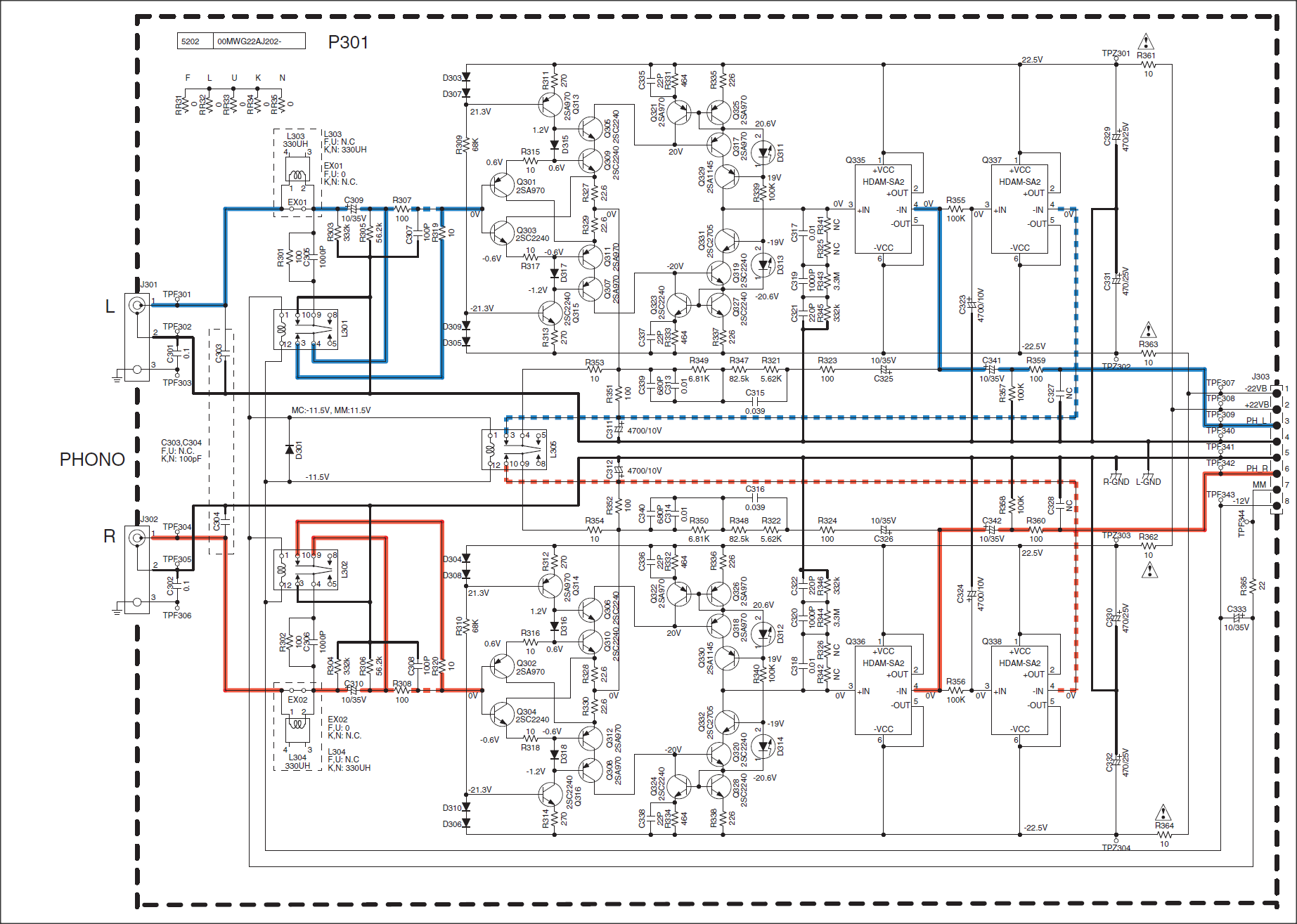
I see caps in the input and output (C309 C341)... why the servo ?
I see caps in the input and output (C309 C341)... why the servo ?
Your right, there is an input and an output cap.
The input cap may be needed because they like the sound of it. They want to prevent saturation of the input circuit by adding the cap (by DC offset's of the source or there own local feedback), or they suspect input signals with huge offset's, or they like the sound of it (who knows). For these reasons I think the cap should be selectable (but who is going to do that in a consumer market product). Maybe even a selection of different cap's. JMO.
The output cap may be needed due to the fact that it was needed (in there opinion). I can not see a reason for the cap, the whole thing is servo'ed and one would expect (by that) a very low output offset. One thing seems to be sure (by this) the input circuit is generating huge offsets, these offset may lockup the circuit, and for that reason the servo was needed.
The output cap, although not needed, is still there. The servo makes it redundant (IMO). So it has to be an oxymoron (Oxymoron - Wikipedia, the free encyclopedia), this may well be the first Oxymoron powered High-End audio circuit in existence
") (actually, I do not know).
(actually, I do not know).As you can see, I DO NOT KNOW (for sure and can only guess). The question(s) need a way smarter person (to answer it) than I am (obviously
).Most probably, they see the cap's as some sort of protection feature.
I think I am in a bit of a sarcastic mood today
I see caps in the input and output (C309 C341)... why the servo ?
This is about the circuit in 10456 http://www.diyaudio.com/forums/analogue-source/154210-mpp-1046.html#post4284257, large picture:
http://www.diyaudio.com/forums/attachments/analogue-source/476063d1428335289-mpp-marantz-phono-stage.png
The output is regulated for DC by Q337 (Q338). But if the output is shorted dc
will always be zero (in other words can not be detected by Q337) and drift of
the circuit may offset the whole thing and drive it into an unpredictable state.
The output cap C431 (C432) may be useful to prevent damage of the buffer
Q335 (Q336) in this case.
Input caps C309 and C310 are used for safety also. The manufacturer of a
commercial product can not prevent anybody from accidentally connecting say
a preamp output to this input. The caps may be useful to prevent damage again,
but perhaps they are used only because it is or was common practice.
The servo is NOT really a traditional servo, has no gain, but is an effective voltage to current converter, iam not so sure how effective it is terms of handling applied offset from external sources, this could explain the input caps. Making the servo this way gas a gross benefit as it shifts the current through the devices so the upper and lower half has the same gain, device matching by running then on different currents, mighty clever.
This is also how I made the housekeeping on the paradise, but this is smarter as it is stiffer currentvise, than voltage through a resistor from an opamp.
This is also how I made the housekeeping on the paradise, but this is smarter as it is stiffer currentvise, than voltage through a resistor from an opamp.
This is why I wrote it is "a follower connected as a DC correctiveThe servo is NOT really a traditional servo, has no gain, but is an effective voltage to current converter,
amp (kind of servo), Q337, 338 in pic of post 10456." in my post 10461 http://www.diyaudio.com/forums/analogue-source/154210-mpp-1047.html#post4285795.
It can be done this way with a "conventional" servo also I think .... this is smarter as it is stiffer currentvise, than voltage through a resistor from an opamp.
Yes this is what we did in the paradise, but there the "Nachteil" is a softening of the driving currensource
I do the same as this in another phono-stage, where I reference the output of servo-opamp to ground an let the opamp-PSSR stiffen the current injection (subtraction) into the circuit.
I do the same as this in another phono-stage, where I reference the output of servo-opamp to ground an let the opamp-PSSR stiffen the current injection (subtraction) into the circuit.
Last edited:
A link to this particular -paradise- circuit would be useful.
If I think about this
shift the dc level at the emitter point of Q309, Q311 through R351, admittedly only
a little bit (low impedance point). The driving impedance of Q337 with R351 is low,
but not very low. On the other hand a conventional opamp servo acts as current
source when a (large) series resistor is applied.
If I think about this
I don't completely agree, because the follower Q337 is a voltage source and it canThe servo ... is an effective voltage to current converter ...
Making the servo this way has a gross benefit as it shifts the current through the devices ...
it is stiffer currentvise, than voltage through a resistor from an opamp.
shift the dc level at the emitter point of Q309, Q311 through R351, admittedly only
a little bit (low impedance point). The driving impedance of Q337 with R351 is low,
but not very low. On the other hand a conventional opamp servo acts as current
source when a (large) series resistor is applied.
So it is here: http://www.diyaudio.com/forums/analogue-source/218625-paradise-builders-2.html#post3189527,
now I remember I had to debug one, the board was not correctly stuffed and the amp
had an oscillation problem also.
The diagram is hard to read but you see a conventional servo driving a low impedance
point with large resistors in series: current drive.
The servo amp in pic of 10456 has no gain (where a conventional servo has large dc gain).
This means that the corrective voltage is as low as the output offset itself and you will not
find many points where dc feedback can be applied effectively. I have no idea why they did
it this way in http://www.diyaudio.com/forums/attachments/analogue-source/476063d1428335289-mpp-marantz-phono-stage.png wasting expensive
HDMAs and requiring bulky caps C311, 323 also.
Last edited:
Well it is a phono-stage, so you have plenty gain at low frequencies, in input cap is to protect the cartridge from DC current.
The paradise servo is injected into the current source driving the circuit, so it works by skewing the currents, rather than injecting DC into the signal like the marantz does.
The paradise servo is injected into the current source driving the circuit, so it works by skewing the currents, rather than injecting DC into the signal like the marantz does.
In the input stage of http://www.diyaudio.com/forums/attachments/analogue-source/476063d1428335289-mpp-marantz-phono-stage.png
the maximum current in the input is the difference in base currents of Q301
and Q303, it will be less than one microamp with reasonably matched transistors,
so an input cap is not necessary for the function.
the maximum current in the input is the difference in base currents of Q301
and Q303, it will be less than one microamp with reasonably matched transistors,
so an input cap is not necessary for the function.