It is the voltage reference (offset from Vout) for the voltage source that feeds the CCS.
Thank you Frans
If I wanted to replace it by three leds what should be the value of the bypass cap ?
Hi Joachim, this question is intended only for learning purposes.... I am not suggesting anymore modifications to the actual design
")
This is a complex design. Any changes we make can create problems. Especially a low output impedance shunt can wreck havoc when it does not 100% fit.
For example the rather simple Nobrainer has being build by some and you will not imagine how many problems came up from not connecting the constant current source Fets the right way around ( layout mistake ) to using a group buy solder that had conductive resin !
This is also the reason i am not posting any new schematic at the moment. I will concentrate to help people that build the Paradise so that it works as intended.
This one is really low noise :IRL 81 A - Infrarotdiode, 1,0mW - sr - 1,5V - 880nm - Fotodioden etc. bei reichelt elektronik
It also has a very steep forward voltage curve against current so it is even a good constant current source. And yes, Benedetto, it is expensive.
It also has a very steep forward voltage curve against current so it is even a good constant current source. And yes, Benedetto, it is expensive.
First 200 NPN sorted.
I am sure I will be able to match every transistor in the two channel paradise.
Relevant parts count:
4,5 25
4,6 24
4,7 31
4,8 23
4,9 27
5,0 13
5,1 19
5,2 12
PS:
Joachim... I wrote that I do not wish to suggest any modd to the already established design.... I was only looking for an answer to ease my curiosity.
BTW.... I like those infrared leds.
Thanks, Jose`.
Yes, Ricardo, that can happen.
I use the Peak Atlas. When the battery is empty it totally stops to work.
I am now selecting the transistors from Reichelt.
Not so much luck here. The PNPs are very good, so far between 490 and 550. That gives good matches with the NPN from Frans, that where a bit higher and found no matches so far. BUT no NPN better the 300, that´s poor.
From the lab (yes they started bright and early in the New Year)
Happy new year to you and everyone around you
And I do have a New Year’s present.
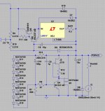
Extensive research in the new year has led to the discovery of an small but useful improvement to the power supply.
The line regulation under extreme load can be improved significantly by replacing the 2.2K resistor with a 2mA current source. Line voltage ‘swing’ under extreme load (50mA AC on top of 50mA DC) goes down from 346uV (already very low) to 27uV (and that is extreme low).
The current source can be created by replacing the resistor with a J310 fet that has an 1.5K gate-source resistor connected (see detail schema).
P.s. I already informed Hesener and he will make the change.
P.s. Joachim this solves the ‘not so low floor’ problem in the previous FFT, the FFT floor is now about 33dB lowered. See: 3988.
Happy new year to you and everyone around you
And I do have a New Year’s present.
Extensive research in the new year has led to the discovery of an small but useful improvement to the power supply.
The line regulation under extreme load can be improved significantly by replacing the 2.2K resistor with a 2mA current source. Line voltage ‘swing’ under extreme load (50mA AC on top of 50mA DC) goes down from 346uV (already very low) to 27uV (and that is extreme low).
The current source can be created by replacing the resistor with a J310 fet that has an 1.5K gate-source resistor connected (see detail schema).
P.s. I already informed Hesener and he will make the change.
P.s. Joachim this solves the ‘not so low floor’ problem in the previous FFT, the FFT floor is now about 33dB lowered. See: 3988.
Attachments
Last edited:
Yes, they have. They are PPS, that is new material from Japan that substitutes Polycarbonate. Maybe they need that in cars.
It is very temperature stable and has low distortion ( Bateman et.all. ).
It has higher DA though then PP or Styroflex. I use Rifa PPS in the signal chain and it sounds transparent ( not there ).
It is very temperature stable and has low distortion ( Bateman et.all. ).
It has higher DA though then PP or Styroflex. I use Rifa PPS in the signal chain and it sounds transparent ( not there ).