Hi, i have the Hypo working on the ULN and the result is positively shocking. Such drahma and transparency, much better then with the Lead Acid batteries. One reason is of cause that the supply hit the design target. I get 17,3 and 17,2 Volt so this is fine.
CCSs get warmer then the shnts so this is ok i think. Tell me what to exactly measure and i can tell you the current in the CCSs. Anyway, i have not much freedom because the little transformer gets very warm already. It is specified for 12VA and it idlles on 10VA now. Will try 30VA block split bobbin tranformer tomorrow.
P.S. my circuit has more gain with more PSU voltage and i asume that the gain whent up by 6dB at least. Fully cranked noise is very low and similiar in both channnels.
The Vdrop on setting resistor, and divide by the setting resistor's value you settled with, will give the running current.
In general, as I have printed on those variable V1 CCTs I posted for you to make some lab supply, the CCS current derives from the difference of the 3 LEDS total Vf drop minus Vgs of each CCS Mosfet, divided by Rset.
Nice to hear about the good sound. I trust you used short enough cables this time too. The CCS has to get warmer than the shunt because it runs the full current times Vin-Vout, when the shunt part shares with the load.
Yes, i understand the current separation between the CCS and the Shunt but i will measure tomorrow. I really like to listen a bit now. Thanks for the short description. I really do not find the time at the moment to go thruw long threads and yours are the longest so people are really interested what you do and i can understand why. I am happy that i found such a good PSU designer like you. Safes me a lot of time and gives phenomenal sonic results with seemingly simply circuitry.
The threads get inevitably long when many people try to understand and to make something. We can't avoid that.
It looks like you use heavily biased circuits in general, its the noise battle I guess....
Is this circuit you listen to now, less in PSRR than the one before? Seems like more affected by PSUs?
It looks like you use heavily biased circuits in general, its the noise battle I guess....
Is this circuit you listen to now, less in PSRR than the one before? Seems like more affected by PSUs?
Yes, the bias in the input stage is 30mA, in the intermediate stage 90mA and as much current as the buffer uses at the output. The new buffer i am designing needs 70mA so we talk about 190mA current draw from a +-17V supply so a stereo stage draws 380mA, that is 12,92 W of power in total. The resut is an SN of -80dB ref 1mV, flat RIAA to 25Mhz and -100dB THD up to 100kHz @ 1V out into 100 Ohm. With a 1kOhm load this vanishes into -120dB. Distortion into 1Kohm is only second and third monotonically falling because of slight deliberate asymmetry although it is a parallel symmetric circuit. AHHH, here comes my Asymmetric Univers Therory again ! I measured around 200mV RMS with my fast meter at the ouput of the stage when sound is really loud in my room so my 100dB/8Ohm MPL and the high gain in my Tube Poweramp help the ULN out to distort even less and this is with the exeption of the buffer an OL circuit. PUH, i worked on that since May 2009 and much of that work is documented here. Perhaps we should publish this thread as a book! Kind of self wrigting book that whould be. No Edditor, no Publisher, nothing. A Non Book !
You asked me if the new circuit has less PSU rejection then the other one ? Maybe. I used an extremely well regulated buffer at the input of the "Hulk" but that bought me 6dB worse noise plus a more complex signal path. I hoped to get more speed that way, but the sim result was similiar so i went back to the more straight forward solutions. Circuits wilh that kind of speed behave totally different when put on a PCB. That is the advantage of "Open Air" construction ( i HATE dead bugs, i think each even small animal should have a chance to live ) and putting this on a PCB by preserving the sound is my next project that will maybe consume more time then the development.
Perhaps we should publish this thread as a book!
FWIW, I captured most of this thread in a word document (though it does not include your latest endeavours with power supplies), and I took the liberty to do some "editoring" of the text (after all I was trained as a teacher) all for my own use but I can send you a copy if you are interested.
Last edited:
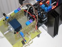
Salas PSU with shortened leads
Again an audible improvement. Soundstage more deep and stable. Details and treble came clearer.
Thanks for your advice, Salas")
Tomorrow I will try LC Audio PSU with short leads.
Wkr
Sam
Thanks for listening. Your cables to the load are too long. Shorten and listen again if you may.
*Cut off the black board's excess if you aren't to implement the DCB1 part, it will come handy.
Again an audible improvement. Soundstage more deep and stable. Details and treble came clearer.
Thanks for your advice, Salas
Tomorrow I will try LC Audio PSU with short leads.
Wkr
Sam

Did you try the sense-force trick ?
well, that is really compact so it will not make a difference perhaps.
It will.
No, I did not do the sence- line.
I want to build up a new board for that, but the the big blue C has no 9240 in stock. I have to look for an other source. But I will not get them before my vacation. So this test has to wait a bit longer.
Joachim, if you are interested how the PCB version sounds, I can send the complete board (linestage + psu+ transfo) for listening. During vacation I am not at home, and I can lend it to you.
Wkr
SAm