So a BIG elco is needed to handle this noise, and also add some speed to the batteries output, as Joachum said. Otherwise you are depending on a chemical reaction, which is not exactly fast in our terms.
I couldn't agree more with both of you.
Regards,
Audiofanatic")
I couldn't agree more with both of you.
Regards,
Audiofanatic
Last edited:
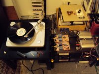
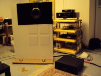
Today i listened a lot to music and started to decide what i bring to the Frickelfest. Sure, i bring my MPL with dipole subwoofer. I am now using MKV caps for the tweeter feed and they sound wounderfull. I also ordered some better coils from Mundorf but i am perfectly happy with my wax dipped self made air coils. Let´s see if the Mundorf coils bring an improvement.
I was planning to bring my JG-Self but i had some bad luck. I had just rewired the input to be able to switch between the Ina and the simple balanced stage. That is an interesting comparison. I still prefer the Ina slightly, it sounds a bit fuller and warmer without loss of detail. Then one clip of my batteries got loose and made a short circuit.
Everything broke down with a very loud cracking noise. Today i started repair but this is a complex beast and i still have some problems with offset.
So i connected my Ultra Low Noise Rosi to the Inductive RIAA and that into my High Speed Preamp. The result is fantastic. Very analog sound with a huge soundstage. As i already mentioned Inductive RIAAs seam to have the edge in midrange resolution. Somehow the energy center is shifted from the treble downwards to the midrange and that sounds very convincing on my system that is not shy in treble. Anyway, i have a good replacement and maybe i can repair the JG-Self and bring it too. Also today one of my LA Audio Tube Monoblocks stopped to work so i have to use the Beredsen Special Edition. A lot of colateral but that is normal when you do fundamental research like me with constant changes.
On another issue i had a long discussion yesterday night with Jürgen Hensler. I am building a Low Z Discrete Ina with Balanced Inductive RIAA at the moment and i need a lot of high value elcaps at the input. Jürgen sugested a transformer instead. First the idea was to use a 1:1 Transformer but after a lot of calculation we found that this is not easy if we want low impedance at the input for lowest noise and wide response in the bass. A 3.6 ohm winding would need over 100mH to reach down to 20Hz -3dB with a cartridge like the Titan i. After a lot of head scratching we found a 1 : 2 transformer could be done and we found a Lundahl model that could do the job. If we put the primary in series and the secondary in parallel we get 3.6 Ohm resistive impedance primary and slightly over 50 Ohm secondary. That has also the advantage that the Opamps in the INA need not to drive such high current that is necessary in the active version. Frequency response in the treble should be very wide with such a low voltage gain and the low impedances used. Theoretical the transformer could reach 500kHz -3dB but we expect more something like 250kHz -3dB.
I will post that circuit and pictures of my Frickelfest system later.
What i do not know is what turntable i will use. I am afraid my Spiral Grove could get some damage and my little Rega is not exactly what i would like to use eather. Maybe i ask Frank Schroeder for help.
This circuit shows the priciple. The RIAA is an older differential design. I will show the Balanced Inductive when it works. 8 Fets may not be neccessary because the transformer has a voltage gain of 6dB. 4 or even 2 whould do as well.
Attachments
Today Jürgen Hensler and I were able to "repair" my LA Audio mono blocks. The problem was really stupid. The Bias in one channel was much to low and the other was way off too.
We adjusted the 6550 tubes to 60mA and everything was fine. In Triode mode the amp can put out 15V and in Pentode 25. The squarewave in Triode looked perfect with -3 dB at 50kHz. In pentode it got to 60kHz -3dB but with a damped overshot so i decided to use it in Triode mode. The sound is very good now and i was in swapping mood. I replaced the Golden Dragon E83CC input tube with a NOS Siemens ECC83 and the gain in sound was substantial. The bass was tighter and clearer and the midrange fleshed out, the treble extended. Then i replaced the ECC82 Ultron differential stage with a very rare Telefunken ECC802S and the sound got really amasing. There was now so much detail and dynamics that ii was a joy to listen. I still have not got the purity that Allens amp has but i can live with what i have now very well. I still plan some improvements. The simple diode bridge will be replaced by hyper fast soft recovery diodes, the coupling caps to the output tubes will get 10nF Silver Mica shunts and the elcaps in the Anode supply will by bypassed too. I will bring this amp to the Frickelfest including the old tubes so i can demonstrate the effect.
We adjusted the 6550 tubes to 60mA and everything was fine. In Triode mode the amp can put out 15V and in Pentode 25. The squarewave in Triode looked perfect with -3 dB at 50kHz. In pentode it got to 60kHz -3dB but with a damped overshot so i decided to use it in Triode mode. The sound is very good now and i was in swapping mood. I replaced the Golden Dragon E83CC input tube with a NOS Siemens ECC83 and the gain in sound was substantial. The bass was tighter and clearer and the midrange fleshed out, the treble extended. Then i replaced the ECC82 Ultron differential stage with a very rare Telefunken ECC802S and the sound got really amasing. There was now so much detail and dynamics that ii was a joy to listen. I still have not got the purity that Allens amp has but i can live with what i have now very well. I still plan some improvements. The simple diode bridge will be replaced by hyper fast soft recovery diodes, the coupling caps to the output tubes will get 10nF Silver Mica shunts and the elcaps in the Anode supply will by bypassed too. I will bring this amp to the Frickelfest including the old tubes so i can demonstrate the effect.
The JG-Self is working again. The output had substantial DC offset so i was asuming that the error was in the output stage. In fact the LME49713 opamps where faulty and i replaced them with LME49710 because i have no LME49713 spares. It works fine but i will substitude them for LME49713 in matal cans i expect to get next week. The LME 49710 sound different, a bit more nervous so i will replace them soon. Maybe the LME49713 sounds more solid because it can drive 100mA of current compared to the 25mA of the LME49710. Another explanation is that the transimpedance amp can drive my 2 5m interconnects with substantial capacitance more easily.
Today i had enough. The LME49710 in this amplication does not cut the mustard. I drive 2 5m long cables with this Preamp, one with a 10 Ohm resistor to the woofers and one with a 75 Ohm resistor to the tube amps. Maybe the LME49710 simply can not drive that. I took the LME49713 from the inductive RIAA and everything is fine. Much more relaxed sound. The LME49713 is really neaded in my system.
Today i had enough. The LME49710 in this amplication does not cut the mustard. I drive 2 5m long cables with this Preamp, one with a 10 Ohm resistor to the woofers and one with a 75 Ohm resistor to the tube amps. Maybe the LME49710 simply can not drive that. I took the LME49713 from the inductive RIAA and everything is fine. Much more relaxed sound. The LME49713 is really neaded in my system.
Hello Joachim
I assume the 10 ohms and 75 ohms are in series with the woofer and the tube amp respectively.
May I ask what the input load resistance of each is respectively, and the capacitance of your cable.
Regards
AR
Yes, the resistors are is series with the cable. The Tube Amps have 330kOhm input impedance and i asume that the woofer crossover has around 47kOhm.
Both cables are 5 m long so when we asume 100pF per meter we get to 1nF and that is considerable. I could of cause measure the cables for more accurate numbers.
Both cables are 5 m long so when we asume 100pF per meter we get to 1nF and that is considerable. I could of cause measure the cables for more accurate numbers.
I will post that circuit and pictures of my Frickelfest system later.
Joachum, looking at this circuit, I see you are not taking any advatage of differential action. After the input traffo, you have two completely DIFFERENT signal paths right to the output - even with separate RIAA networks per "half".
There is no way you can make these two halves exactly identical, so sooner or later in the signal path these signals will have to come together (maybe not until the tube amp's output traffo. But then you will get some signal cancellations and some signal boosting, which I doubt if that's what you want.
That is why all my balanced circuits are real differential, with each "half" of the balanced signal being coupled to the other half. Also why I don't like conventional Push-Pull amps, there is always signal cancellation to a greater or lessor degree for the same reason.
Posted the preamp to you today, no problem.
Regards, Allen
Today i had enough.
Well, so do I
Not even the opamp rollers fanatics ever dared to directly substitute a voltage feedback opamp (LME49710) with a current feedback opamp (LME49713) and then (assuming the thing is stable) claim a "more relaxed sound".
Speaking about stability, current feedback opamps are about the worst you can get to drive capacitive loads like long cables. There are enough high output current voltage feedback opamps that you can successfully use.
Really Joachim, this is a friendly environment, but at the trade shows you are participating you may encounter an engineer and the whole thing may blow in your (red) face. Not to mention your next sound reviewer potentially using a supa-dupa cable and, due to the capacitive loading, getting a horrible screech instead of a clean sound.
Good luck!
Hi folks ! Thank you that you care about my sound and even about my reputation.
A passive transimpedance RIAA could be done like you do Allen and Russ White of Twisted Pear has exactly done that in his Retro stage. What you loose is overload margin, not a big problem in your tube designs that have generous voltage swing i hope. I could be persuaded into a hybrid aproach with passive 75usec and the rest done active. Cancelation whould ocure more in the treble i guess. Even then you whould loose 14dB overload margin in the treble. I have done circuits like that and i must admit that they worked fine in practise. On the other hand, the latest Mark Levinson CD player has a fully differential anti alias filter and measurement look fine. The final circuit will not have that RIAA topology anyway. It has one inductor and one capacitor that is shared by the positive and nagative side. Actually it is so stupid simple that i first whould like to build it until i post it, so watch this space.
To SYN08 : The original circuit was designed around the LME49713 in mind. With a high enough feedback resistor i had no stabilty problems. The 10 Ohm output is for a headphone that the LME49713 can drive just fine with it´s 100mA current output. The LME49710 i substituted may have benefitted from a 75 Ohm resistor in that line too, but i did not try that because i wanted to ceep the headphone output. I have critisised other Opamps swappers of careless praxis without measurements and now i fall in the same trap. Thank´s for alerting me. I should not talk about the sound unless i am sure the circuit measures well or others ask me.
See the circuit i build. The quite high feedback resistor makes sure that the current feedback Opamp does not oscilate.
Attachments
Hello Joachim,
Syn08 has beaten me to the punch , both the LME49713 and the LME49710 talk of being able to drive 100pf in their respective data sheets and I would say both opamps would have both as much difficulties driving 1nF directly without additional precautions, the +/-100ma current output capacity of the LME49713 does not mean it can drive a capacitive load any better than device that can only drive +/-26ma like the LME49710.
Regards
AR
Pheonix, you are right, they need decoupling resistors to drive that load. Still, whenever i use the LME49713 as output chip, i prefer the result over other alternatives provided the circuit is stable. I use the LME49713 also in my High Speed Line Preamp with a BUF634
buffer in a feedback loop. With some compensation and an output Zobel i got a frequency response up to 25MHz -3dB. Squarewave response is clean and i am able to drive 2m long exotic cables without problem. I did not try longer cables though because the Line Pre is not far from my mono blocks. A big challenge was the volume control because potmeters in a standart arangement have high stray capacitance at very high frequencies so i designed a shunt volume and balance control. Here a compromise between input impedance and noise has to be found. An input buffer can be used if a source with a high output impedance is to be used like a CD player with a tube output stage. I also encountered problems with crosstalk in the balance control and i solved that satisfactory too. A major project that whould deseve it´s own thread but i am too busy at the moment.
Comming back to phono stages, i have not shown a balanced input stage without negative feedback except the balanced transimpedance BJT stages at the beginning of this thread. I am working on the input stage of my INA at the moment because before i try the transformer input i wanted to be sure that this stage works as well as posible. I especially investigated the Low Z variety because that is the starting point of the transformer balanced variety. Having worked with Malkolm Hawksford in the 90th i always wanted to try the Hawksford cascode but no success here. Whatever i tryed, i always came back to my original design so i am confident now that it works just fine.
I have shown how to use the input of the discrete INA as a conventional unbalanced open loop Head Amp. Just connect the gates of the input Fets together and use two caps for output coupling. A balanced version needs a diffential output stage to extract the signal or you only hear the common mode signal, in this case virtually nothing.
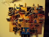
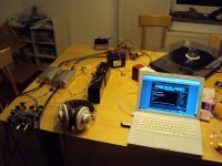
Having had success with a simple diffential amp as the input stage of a phonoamp i build just that at the output of the Discrete INA input stage. I had some ADA4898-1 left over from my rebuild JG-Self input stage that already have decoupling caps on board so i simply used them. R19 and R20 are in series with the signal so contribute some noise. I could try to reduce the impact by making them lower in value and redimension the resistors around the ground referenced common base stage but i stopped here because i just wanted to know if this works. Noise could be further reduced by putting buffers in front of R19, R20 and then reduce them to say 200 Ohm or less. The input stage itself is superbly low in noise because this time the impedance of the cartridge is in parallel to the feedback resistor and not in series like in a convential circuit so actually connecting the cartridge lowers the noise. The disadvantage is the big elcaps that are needed at the input for good low frequency extention. Other users may not like the low input impedance but if the transformer works both issues are solved. I was very curios how this circuit sounds but the family was already sleeping so i set up a little system on the dining table and listened with headphones. It works and noise from the record over headphones masked the remaining noise very well ( or should i say very badly). This circuit can be rewired to High Z by desoldering the gates from ground and using them as input plus loading resistors. Maybe it is better to substitude the 10 Ohm resistor with a trimmer that has the middle pin to ground and can trimm the input stage in this case but i did not try eather.
buffer in a feedback loop. With some compensation and an output Zobel i got a frequency response up to 25MHz -3dB. Squarewave response is clean and i am able to drive 2m long exotic cables without problem. I did not try longer cables though because the Line Pre is not far from my mono blocks. A big challenge was the volume control because potmeters in a standart arangement have high stray capacitance at very high frequencies so i designed a shunt volume and balance control. Here a compromise between input impedance and noise has to be found. An input buffer can be used if a source with a high output impedance is to be used like a CD player with a tube output stage. I also encountered problems with crosstalk in the balance control and i solved that satisfactory too. A major project that whould deseve it´s own thread but i am too busy at the moment.
Comming back to phono stages, i have not shown a balanced input stage without negative feedback except the balanced transimpedance BJT stages at the beginning of this thread. I am working on the input stage of my INA at the moment because before i try the transformer input i wanted to be sure that this stage works as well as posible. I especially investigated the Low Z variety because that is the starting point of the transformer balanced variety. Having worked with Malkolm Hawksford in the 90th i always wanted to try the Hawksford cascode but no success here. Whatever i tryed, i always came back to my original design so i am confident now that it works just fine.
I have shown how to use the input of the discrete INA as a conventional unbalanced open loop Head Amp. Just connect the gates of the input Fets together and use two caps for output coupling. A balanced version needs a diffential output stage to extract the signal or you only hear the common mode signal, in this case virtually nothing.
Having had success with a simple diffential amp as the input stage of a phonoamp i build just that at the output of the Discrete INA input stage. I had some ADA4898-1 left over from my rebuild JG-Self input stage that already have decoupling caps on board so i simply used them. R19 and R20 are in series with the signal so contribute some noise. I could try to reduce the impact by making them lower in value and redimension the resistors around the ground referenced common base stage but i stopped here because i just wanted to know if this works. Noise could be further reduced by putting buffers in front of R19, R20 and then reduce them to say 200 Ohm or less. The input stage itself is superbly low in noise because this time the impedance of the cartridge is in parallel to the feedback resistor and not in series like in a convential circuit so actually connecting the cartridge lowers the noise. The disadvantage is the big elcaps that are needed at the input for good low frequency extention. Other users may not like the low input impedance but if the transformer works both issues are solved. I was very curios how this circuit sounds but the family was already sleeping so i set up a little system on the dining table and listened with headphones. It works and noise from the record over headphones masked the remaining noise very well ( or should i say very badly). This circuit can be rewired to High Z by desoldering the gates from ground and using them as input plus loading resistors. Maybe it is better to substitude the 10 Ohm resistor with a trimmer that has the middle pin to ground and can trimm the input stage in this case but i did not try eather.
Attachments
Errata : C3 has to be left out or another cap has to be added in the positive chain. The servo can then be removed. The small cap over the negative feedback resistor of the ADA4898-1 is needed because it easyly oscilated with feedback resistors higher then 150 Ohm. Quite unusual but you can find that advice in the spec sheet. At first i had a very nice MHz sinewave with full voltage output.
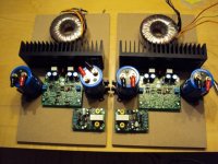
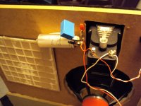
Now with the Audionet MAX2 permanently on load to a friend that neads high power on his 89dB efficient speakers more then me and the Mace Amp still not repaired ( the Berendsen goes back to another audiophlile), i need a reference solid state amp in case i develop a more conventional speaker then my MPL. I decided on Jan Diddens Pax. Actually i had started to build it a while ago but did not find time to finish it. Now i have all the parts and Jürgen Hensler was nice enough to drill the holes into the cooling profile today.
After some thought i did the basic layout. The hyper fast diodes are simply bolted to the cooling profile. They need some isolation though. The transformer is on the oposite side of the cooling profile to have it far away from the input.
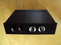
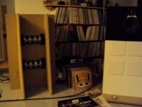
I am also building a case for the JG-Self. The photo is not that good but in reality it looks decent. I will add a mono switch and an input switch for CD. The volume controls are seperate with dials.
I have trouble uploading the photos. I will try later. Maybe i can make a better photo of the pre.
After some thought i did the basic layout. The hyper fast diodes are simply bolted to the cooling profile. They need some isolation though. The transformer is on the oposite side of the cooling profile to have it far away from the input.
I am also building a case for the JG-Self. The photo is not that good but in reality it looks decent. I will add a mono switch and an input switch for CD. The volume controls are seperate with dials.
I have trouble uploading the photos. I will try later. Maybe i can make a better photo of the pre.