Thanks Sergio.
So for SOT23, the best choice is still 2SC3324 / 2SA1312 ?
Patrick
The 2sc3324 has lower noise than the ztx851 if the source resistance is higher than 1k , the ztx851 is only good for low source resistance applications like a MC amplifier, what are you looking for ?
Hi,
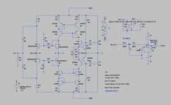
I simmed the circuit from #10628 and Martin´s assumption that compensation might be tweaked seems right.
Adding a 47k/100pF load to the output and the circuit goes nuts.
C1 is certainly too large in value, 82pf seems more common.
R11/C2 don´t affect much at all.
Looks as if a RC series network between the Input´s collectors of Q1-Q6 is most promising.
Also changed the JFET to a OnSemi MMBF4391LT1 a imho better choice for a JFET ccs.
Still though amplitude response keeps on peaking/circuit oscillating.
Noise simulation results in impressively low values though (0.27nV/sqr(Hz)
jauu
Calvin
Calvin, you should increase the Ic of the input transistors to 10mA per BJT for the lowest possible noise.
The miller capacitor value that you use looks to small, the input stage transconductance is very high and there is no degeneration resistors, so the miller cap has to be higher than normally, have you test the open loop gain?
Cordell's models for the BC550C/560C had about 150 Rb. I thought the BC850C was supposed to be the same chip, so how did Rb get up to 660?
The Rb of 660 was measured in a infinion BJT, the ONsemi specifies lower noise than the rest of the companies that produces the bc850/bc550 , and in the datasheet of ONsemi the Rbb is 150 ohms @ 3mA . I think that Cordell never measure the bc550c he made the models based on the datasheet.
Now with all trimmings.
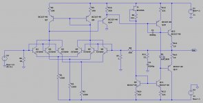
It's a transimpedance amplifications stage. The impedance of the generator coil is influencing the gain, so with lower output MC's the gain will typically be higher.
I do have a good feeling about the noise, as the RC-filtering of the bases will essentially shunt all the noise from the housekeeping to the GND.
Here with the biss transistors from NXP. They too are low in noise though i don't have Rbb data, But I have built a Phonostage with them earlier where the proved very very quiet (zetex quiet)
I inserted the servo, just for the exercise of it, it takes input offset from around 500uV to about 1uV
Attachments
Last edited:
The idea of taking the caps out, is good, but I am not really convinced about the practical benefits. It puts a lot of DC strain on the servo for the second stage so it can pull the circuit off balance.
I also like the cut @ 10-15 Hz that sort of reduces the problems with a poor cart/arm combination that the caps provide for "free" you can also argue to lengths what is "worst" caps or the extra output stage formed by the folded cascode. (G**D, need to build this one ALSO the get the right answers)
I also like the cut @ 10-15 Hz that sort of reduces the problems with a poor cart/arm combination that the caps provide for "free" you can also argue to lengths what is "worst" caps or the extra output stage formed by the folded cascode. (G**D, need to build this one ALSO the get the right answers)
Michael it was only a suggestion ") , I dont have problems with capacitors in the audio patch, there are very good capacitors, I personally prefer the capacitor solution.
, I dont have problems with capacitors in the audio patch, there are very good capacitors, I personally prefer the capacitor solution.
In my phono amp, in the beginning I have used a DC servo with a resistor of 1Mega ohm and a capacitor of 1uf, but there was a lot of subsonic frequencies at the output especially with small warped discs, changed the capacitor to 220nf by recommendation of Joachim and the subsonic problem disappear.
, I dont have problems with capacitors in the audio patch, there are very good capacitors, I personally prefer the capacitor solution. In my phono amp, in the beginning I have used a DC servo with a resistor of 1Mega ohm and a capacitor of 1uf, but there was a lot of subsonic frequencies at the output especially with small warped discs, changed the capacitor to 220nf by recommendation of Joachim and the subsonic problem disappear.
Yes, most servos for phono are too extreme low in frequency. That not only has the problem of subsonic but the reaction is slow too. Maybe too slow to capture thermal drift.
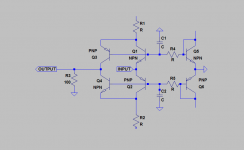
Circuit 10646 can be modified for balanced input when C1, C2, R4, R5 is taken out and the ground connection is used as an input ( i think, spontanious ).
Circuit 10646 can be modified for balanced input when C1, C2, R4, R5 is taken out and the ground connection is used as an input ( i think, spontanious ).
Hiya,Hi,
I simmed the circuit from #10628 ...
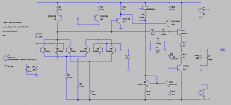
I changed the compensation scheme somewhat and I do not get any oscillation anymore, at least in my sims and with my limited knowledge. So to me the circuit looks pretty stable now. If I remove C1 , R11 I do get some ringing that seems to settle down again (removing or lowering C2 as well and it rings like a bell). I also tried a version with 10mA bias of the input transistors and that looks also stable to me. I am just not sure how much that would improve noise in a real circuit.
I also tried MMBF4391 though I would probably prefer to use current diodes instead. Does anybody know of any SMD current diodes ?
Attachments
Hi,
maybe I made a wrong connection or some other typical-stupid-me kind of failor .... let me check that ... but may take a couple of days though.
Did the sim rather inbetween more important tasks, but iIrc the openloop sim showed phase angles of ~240° @0dB, explainig the difficulties to get the thing quiet.
jauu
Calvin
I am not in a hurry, I also have only limited time. Also, I noted that I posted the right sim but an old version picture, second try:
Where do you see the noisy bias, can you point to it, not sure I understand?
when The biasing is noisy,...
Where do you see the noisy bias, can you point to it, not sure I understand?
Attachments
Last edited:
All the current you run through the input transistors needs to pass 1400 ohm resistors. those ase noisy. low noise designs need to have CCS, this will also improve PSSR, which is the other side of noise. With this design you gain nothing by running multiple input pairs.
By adding more amplification stages you push the OLG up and you twist the phase more, making the design on the edge stability wise, you then need to compensate enormously to gain some kind of stability.thus sacrificing alle the benefits you get from the extra gain.
For an opamp a simple blameless design will be much better and easier to make work. You can also look a PASS DIY-paper on discrete opamps that will give you a good place to start.
Last edited:
The noise of the 1.4k resistors is ignored by the LTP as far as I can tell. Even deliberately imbalancing the LTP does not significantly increase noise.
Indeed, it is a common mode signal for the input stage therefore its noise contribution is negligeable. I calculated a CMRR of 46dB for this particular input stage. This is not a lot in absolute terms but sufficient that it should render the noise contribution from the biasing resistor(s) to a fraction of an ohm (if I got my resistor noise calculations right).
Last edited:
In simulation the most significant noise sources are the source impedance (by far) and R7.
Would the re of the input transistors in series with their rbb not be contributing as well? I thought rbb was not included in the models? Just guessing.