Something more about transistor noise.
http://www.diyaudio.com/forums/parts/168561-some-transistor-voltage-noise-measurements.html
http://www.diyaudio.com/forums/parts/168561-some-transistor-voltage-noise-measurements.html
Martin , I made some modifications at your schematics, and use the FZT849 because it will be more similar to the 2sc6000.
The circuit needs a DC servo or a capacitor at the output. And the resistor r106 should be current source. It need more improvement.
Thanks Sérgio
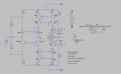
I played a bit with my original schematic replacing the input transistors with FZT849, adding a simple current source in place of R106, as well as adding Q14 as an additional buffer and finally DC coupled the circuit (for now).
And looking again at the pictures of their circuit boards it appears their actual circuit stays pretty close to their diagram, including the resistor biasing of the input pairs (I see they are doing the same in their C27 and I am wondering if they have a particular reason for this). Anyway, my goal was to maintain the Accuphase "flavour" and topology rather than trying to come up with something completely new. Therefore I left the remaining topology untouched, though there might still be a little bit of tweaking to do, e.g. with the compensation of the circuit:
Attachments
yes, you are very close to the original, and you dont need to use the current source use the r106 like they do, you only need to make sure the power supply is really quiet, If you use some capacitance multiplier in serie at the power supply you will have a very quiet power supply.
 The problem is to get the 2sc6000, they look so good.
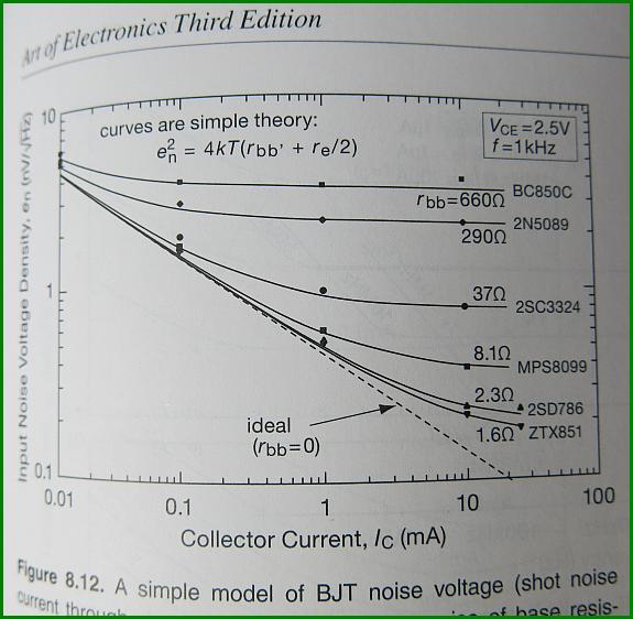
If you want to use transistors from zetex I think the safest is to use ztx851 as jacco vermeulen suggested the rbb is really low at 1.6 ohms, but the hfe is not as good as the 2sc6000 and the Cob is also a little high.
The problem is to get the 2sc6000, they look so good.If you want to use transistors from zetex I think the safest is to use ztx851 as jacco vermeulen suggested the rbb is really low at 1.6 ohms, but the hfe is not as good as the 2sc6000 and the Cob is also a little high.
the FZT951 is rated for max 5A continuous.
At 1A as a switcher it is shown as typically 85mVce and needs 100mA of Ib where Vbe ~750mV.
That gives a total dissipation of ~160mW as a switcher @ only 20% of maximum rating.
It's needs to be a higher dissipation package to operate.
At 1A as a switcher it is shown as typically 85mVce and needs 100mA of Ib where Vbe ~750mV.
That gives a total dissipation of ~160mW as a switcher @ only 20% of maximum rating.
It's needs to be a higher dissipation package to operate.
http://www.diyaudio.com/forums/attachments/analogue-source/529322d1454629603-mpp-ztx-noise.jpg
If the Rbb is the value as stated then the curve is as drawn.
I don't think that the curves are stating that the Rbb shown are typical for these devices. Does H&H shown the derivation of Rbb for those transistor types?
those curves are shown for the formula quoted.Jacco, where did you find those curves..??
Looks like the zeetex parts are low RBB champs...
If the Rbb is the value as stated then the curve is as drawn.
I don't think that the curves are stating that the Rbb shown are typical for these devices. Does H&H shown the derivation of Rbb for those transistor types?
> FZT851/951
Is there a SOT23 equivalent ?
Patrick
Hi Patrick, the Ztx851 and ztx951 are the trough hole equivalent. Don't think they have a sot23.
Hi,
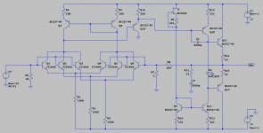
I simmed the circuit from #10628 and Martin´s assumption that compensation might be tweaked seems right.
Adding a 47k/100pF load to the output and the circuit goes nuts.
C1 is certainly too large in value, 82pf seems more common.
R11/C2 don´t affect much at all.
Looks as if a RC series network between the Input´s collectors of Q1-Q6 is most promising.
Also changed the JFET to a OnSemi MMBF4391LT1 a imho better choice for a JFET ccs.
Still though amplitude response keeps on peaking/circuit oscillating.
Noise simulation results in impressively low values though (0.27nV/sqr(Hz)
jauu
Calvin