I am working with my curve tracer to find out how i can make a symmetric N-P channel MosFet pair.
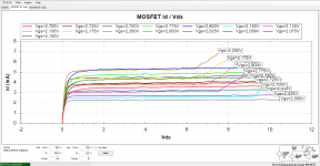
Glad i did. Found a strange kink in the first N-Channel i picked random.
The second sample was fine. Maybe it was fried by static charge.
Be carefull when you use them.
See the overlay of one P-channel and two N-channels. one was faulty.
Glad i did. Found a strange kink in the first N-Channel i picked random.
The second sample was fine. Maybe it was fried by static charge.
Be carefull when you use them.
See the overlay of one P-channel and two N-channels. one was faulty.
Attachments
So are you talking about the input capacitance Cis ?
The N-Channel has 35pF, the P-Channel has 50pF so a 15pF from gate to source of the N- channel would make it ?
In earlier simulation experiments I have simulated 'gate-stoppers' from 100 to 10kOhm and found almost no effects of the extreme high values. For me that is an indication that the input capacitance of the mosfet does not influence the circuit to much. Today I simulated a added Cgs and stepped from 1 to 200p, again there seems to be (almost) no effect, only the extreme 200p value made a 5dB change in the FFT, all other values made a less then 1.5dB change.
The gate stopper is ignored because it does not shunt current. The Cgs shunts current so it is a source of distortion in circuits where it is the dominant load to the preceeding stage.
The same way a current drive amp is unaffected by voicecoil resistance, a collector-driven gate will be unaffected by the gate stopper except at VHF. Yet, it is loaded by Cgs which will cause distortion.
However, in many cases Ig is swamped by other distortion mechanisms so none of this will be important yet.
We can say that gate stoppers only matter after the gate capacitance has become a significant load, only then will there be enough current through the gate stoppers to cause any effect. Thinking of it this way we see that gate capacitance is the stronger effect, and that by the time gate stoppers have any effect on distortion, gate capacitance has already become a very significant load.
I will try this out.
i also have another idea, waiting for parts.
The 100V N channel part has a very close Gm to the 60V P channel .
But the Vgs(off) is still about 0.8V differance between the N/P parts...
can`t you use an apropriate diode to pick up that Vgs slack??
Last edited:
why the mosfets..?? would the circuit not run just as well with BJT
I do like mosfet's
")
My idea is to find the right source resistor before i put the N.Channel into the circuit.
That whould safe time.
Sure,
you first find the resistor to match the Gm and then find the correct bias point of output stage to produce the right voltage drop on that resistor so DC offset is nulled..
If power dissipation allows.
Frans. I do also think Mosfets has some good properties, but they are not very symetric (both in transconductance and VGS) and in that respect worse than BJT. The cool(est) part of this circuit is the mosfet bootstrap the way it's set up it also performs current feedback
Frans. I do also think Mosfets has some good properties, but they are not very symetric (both in transconductance and VGS) and in that respect worse than BJT. The cool(est) part of this circuit is the mosfet bootstrap the way it's set up it also performs current feedback
This circuit started as a diamond buffer, it then was bootstrapped (using the mosfet's) and it was great. The (my) problem was, I thought it was not great enough. So I turned the input transistors around (base to the output side) but I could not get it working, then it came to me that I needed the higher Vgs of the mosfet's to make it work, and so done. This new buffer was really amazing (in simulation). There where no current differentials, there where no voltage differentials (except in the bootstrap's) and it's simulated THD was -180dB at about 1Mohm input resistance and a good driving capability, in short, an almost ideal buffer.
Joachim did test it and it worked great, but he needed ... gain
. The resistor dividers where added, the capacitors where needed to easy bias the thing, many other configurations where tested, suggestion from different people, but this is the one that survived, it works, it is easy to adjust, and it sounds real good.I have both, the diamond with BJts and the MosFet with gain.
I prefer the sound of the Mosfet version even after i have set the gain with an Alps slider to x 1 ( like the diamond ).
The diamond punshes along as they do but the MosFet is even more transparent and " natural ".
Let Martina be the judge. She will visit me soon and we will compare.
I prefer the sound of the Mosfet version even after i have set the gain with an Alps slider to x 1 ( like the diamond ).
The diamond punshes along as they do but the MosFet is even more transparent and " natural ".
Let Martina be the judge. She will visit me soon and we will compare.
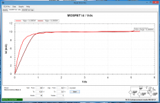
The left diagram shows what happens when i insert a 68 resistor in the source of the N-channel.
Brown is the N.channel.
The quasi saturation knee is a bit softer but from 2V Vds they are quite similar.
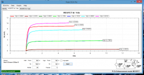
The right diagram shows the situation before degeneration.
The P-channel needs nearly 3V Vgs to have the same idle then the N-channel with 2.3V Vgs.
Brown is the N.channel.
The quasi saturation knee is a bit softer but from 2V Vds they are quite similar.
The right diagram shows the situation before degeneration.
The P-channel needs nearly 3V Vgs to have the same idle then the N-channel with 2.3V Vgs.
What is the open loop gain of the buffer/line-stage..?
Just above 60dB (measured by replacing the feedback/divider resistor by a 1G inductor).