Hesener is a 'schatje'")
lets first see if i can fix it .... ;-)
Thanks, Alfred, that is dedication of a true artist.
I want those babies to play nicely together ;-) And, there might be some interesting information there to improve for the final design....
inverse RIAA
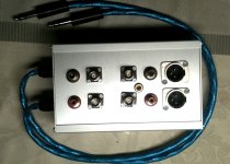
Here is the inverse RIAA box, two fully differential channels. The four connectors on the left side are the inputs (differential through the cables, single-ended via the connectors), right side is outputs XLR/RCA/BNC all in parallel. Now I want to do a few measurements to see if it is precise.....
Did connect a CD player to the input RCAs and the Paradise to the output, it worked fine, tonal balance appeared to be correct (but it was only a very brief listening). What was interesting though is that the sound character of the Paradise (muscular, well-structured bass, and "forward" character in the mids and highs) was still there...
Attachments
I am home and got transistors and diodes from Hesener, thanks.
So, you will be listening to this within an hour or so.
[I am still
 so no transformers in post yet. (Heavy red wine is OK, its the green vegetables, you know, the healthy stuff, makes my foot and knee swell up so painfully]
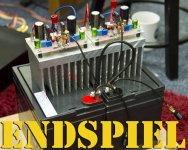
It is a little quiet here so i decided you should have some fun and look at the first power amp i build in 40 years. Actually my power amp career came to an abrupt halt after i had build my first kit at the age of 13. I had saved the little money i had for several month to build a power amp. I soldered it together and fired it up. With a big bang the electrolytic´s went up in smoke. I had connected them the wrong way around. That frustrated me so much that i decided to take the road to speaker building and making low level stages, like preamps, filters and phono stages.
Since then i have repaired and updated several power amps and have studied numerous schematics, books and threads. So theoretical i know about most of what is going on in power amp design. I even had designed a SUSY amp based on power Opas. I have given that circuit to Brianco but again karma struck, preventing Brianco from finishing it. Still there was this spell on me that one friend of mine had formulated : "You are not allowed to design with more then plus-minus 24V and 1A."
I thought that after 40years in no power amp prison i break free and try something.
Actually what i wanted to build is not a complete power amp but a power buffer.
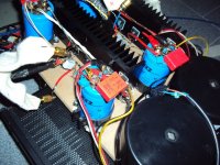
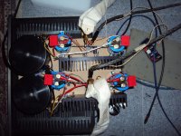
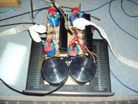
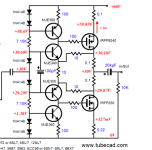
There are several good designs by Macura, Ciuffoli, Tubecad and others. Mostly they are single ended with N-Channels that work on a constant current source. I chose another circuit that i found one day on the web. I drew it by hand and put it away. Recently i discovered it again in a pile of papers and i must say that i like it. It uses only 3 transistors per channel, One N-Channel, one P-Channel and one BJT driver. I will draw the schematic over the weekend. It is a push-pull Class A amp. I run it on plus-minus 33V with 1,65A idle. That draws around 100W per channel so the amp gets rather hot. I think the Fets can stand that because they are robust but i may reduce the voltage somewhat and-or use bigger cooling finns. In 8 Ohm the amp produces around 20W in Class A. That is enough to drive my MPLs without leaving Class A much. So far i could not check
clipping because my generator produces only 20V. I will do that tomorrow when i have made the voltage amplification section. The buffer is fast with -3dB at 7MHz. It has a small overshot so i filtered the input at 1,5MHZ -3dB. I have not measured or simulated distortion but i will measure it ones in a while. If somebody want to do that, please put it in the simulator. It worked right away and does not produce any nasty on-off transient.
There is a small hum, because PSRR is not that great. It has potential for improvement, so when you have any idea, i am open for suggestions.
Here are some pictures.
Schematic comes later.
Since then i have repaired and updated several power amps and have studied numerous schematics, books and threads. So theoretical i know about most of what is going on in power amp design. I even had designed a SUSY amp based on power Opas. I have given that circuit to Brianco but again karma struck, preventing Brianco from finishing it. Still there was this spell on me that one friend of mine had formulated : "You are not allowed to design with more then plus-minus 24V and 1A."
I thought that after 40years in no power amp prison i break free and try something.
Actually what i wanted to build is not a complete power amp but a power buffer.
There are several good designs by Macura, Ciuffoli, Tubecad and others. Mostly they are single ended with N-Channels that work on a constant current source. I chose another circuit that i found one day on the web. I drew it by hand and put it away. Recently i discovered it again in a pile of papers and i must say that i like it. It uses only 3 transistors per channel, One N-Channel, one P-Channel and one BJT driver. I will draw the schematic over the weekend. It is a push-pull Class A amp. I run it on plus-minus 33V with 1,65A idle. That draws around 100W per channel so the amp gets rather hot. I think the Fets can stand that because they are robust but i may reduce the voltage somewhat and-or use bigger cooling finns. In 8 Ohm the amp produces around 20W in Class A. That is enough to drive my MPLs without leaving Class A much. So far i could not check
clipping because my generator produces only 20V. I will do that tomorrow when i have made the voltage amplification section. The buffer is fast with -3dB at 7MHz. It has a small overshot so i filtered the input at 1,5MHZ -3dB. I have not measured or simulated distortion but i will measure it ones in a while. If somebody want to do that, please put it in the simulator. It worked right away and does not produce any nasty on-off transient.
There is a small hum, because PSRR is not that great. It has potential for improvement, so when you have any idea, i am open for suggestions.
Here are some pictures.
Schematic comes later.