Please make space for 4 Leds in series before the servo, just in case somebody is not comfortable with the blue Leds.
For example the AD825 can stand only plus-minus 15V. Some say it has magical properties as a servo because it has an open loop bandwidth of 10kHz. With 12nV/qHz it is a bit noisy though but that does not play a big role here.
Thank you for the extra leds. I was not joking.... Ambar are the lowest noisy ones... blue are the worst.
Is AD825 the chosen one ?
No, i use OPA134 all the time but i will try AD825 too. I do not think that in MiiBs arrangement it will matter much provided the servo chip has a high input impedance and low offset voltage. It is very remote from the amplification chain and by 1kHz the integrator will be rolled of much so even a TL071 should be OK.
Anyway, some people think that the servo IC is audible and the AD825 has that special feature of high open loop break point.
For absolutely lowest offset i recommend the OPA827 or ADA4627.
Anyway, some people think that the servo IC is audible and the AD825 has that special feature of high open loop break point.
For absolutely lowest offset i recommend the OPA827 or ADA4627.
Glad to hear that. Blue LEDs are an absolute no-go.blue are the worst.
 .
.Have been working with the Buffer, could not understand that 44MHz resonant peaking, found out that the resonance was caused by the resistor above the driven cascode. The reason I placed it in the first place was to reduce the voltage over the cascode and thus to reduce heat in the cacsode transistor
I took the resistors out and the 44MHz ringing disappeared, I then reduced heat by lowering the current to 3 mA by inserting a 15Kohm resistor in the mirrored floating current source.
To have enough voltage drive to the output, the spread resistors are upped to 22 ohms.
I took the resistors out and the 44MHz ringing disappeared, I then reduced heat by lowering the current to 3 mA by inserting a 15Kohm resistor in the mirrored floating current source.
To have enough voltage drive to the output, the spread resistors are upped to 22 ohms.
Attachments
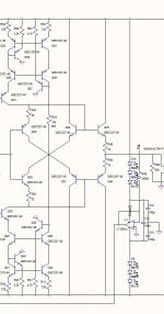
transistors changed to BC327/337, resistors to 470, two trimmers with 2k/10turns, LEDs added
at this point it looks like the 100x160mm PCB might be a little too small.... we'll see....
R47/R51/R19 have new values printed in #3788.
R54 & R55 are removed also on last update from MiiB
Still looking at other parts of scheme...
Hi,
thanks for the comments, the changes from #3788 are implemented. Attached is the BOM. All in all, its 28pcs of BC327 and 337 each.... this is massive.....
floorplanning is proceeding and roughly there, looks like the required dimensions will be around 120mm x 200mm.....
thanks for the comments, the changes from #3788 are implemented. Attached is the BOM. All in all, its 28pcs of BC327 and 337 each.... this is massive.....
floorplanning is proceeding and roughly there, looks like the required dimensions will be around 120mm x 200mm.....
Attachments
Is it possible to provide DO-41 pads for zeners on pcb?
///just checked that on BOM it is included within footprint of do-204
what I am worried is wire dia - it is for some samples I have equal to 0.77mm for BZX85C - should fit, but may be tight with generic max of do-204 0.86mm when we consider thru hole plating which can take up to 0.1mm.
///just checked that on BOM it is included within footprint of do-204
what I am worried is wire dia - it is for some samples I have equal to 0.77mm for BZX85C - should fit, but may be tight with generic max of do-204 0.86mm when we consider thru hole plating which can take up to 0.1mm.
Last edited:
Is it possible to provide DO-41 pads for zeners on pcb?
///just checked that on BOM it is included within footprint of do-204
what I am worried is wire dia - it is for some samples I have equal to 0.77mm for BZX85C - should fit, but may be tight with generic max of do-204 0.86mm when we consider thru hole plating which can take up to 0.1mm.
made the holes bigger (already). I have come across that problem before ;-)
made the holes bigger (already). I have come across that problem before ;-)
That is great. Thank you!
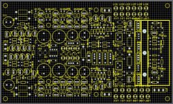
See attached the first draft of the floorplan, size is 120mmx200mm so slightly larger than an "eurocard". You can see the input structure (middle left) along with the large caps, on top and bottom are the two current mirrors each, in the middle between the caps is the servo, to the right of this (center aisle) is the RIAA compensation, and above the RIAA are the two halves of the output buffer. To the right is the heatsink with the current source stuff under the heatsink, and the shunt reg circuitry in front of it, with the two trimmers to set the voltages.
On the connectors, there are two input connectors on the left (to hook up the input and impedance setting), two outputs (top and bottom), to ease the cabling in the case, and the power connector (3 pins) lower righthand corner.
Comments appreciated! I will fix a few issues with some of the footprints now, and start the routing in the next days - too bad there is this strange holiday coming up ;.)))
Attachments
Strange holiday ??
You know, involving obscure men with white beards and illegal flying objects abusing animals with red noses carrying a truckload of goods...
That board looks already nice!
Rüdiger