the plan for today was working on the Salas shunts. my task was to trim the Fet cascodes for the correct 2mA current. that proved to be very time consuming and ultimately boring. after i finished two circuits i gave up for today. not a good work for sunday afternoon !
i decided to have some fun. the inductive RIAA has ample gain (67dB) so it could be directly connected to a power amp with a passive pre. i had build some over the years, the most successful with 10kOhm Alps studio faders. i trick i had copied from John Curl.
they have good tracking and sound very good. you can take two monos and run them in parallel. much better then a balance control at least with conventional technology. i thought an active buffer would do even better and decided to build my version of the Pass-Salas symmetric supply B1. i had admired that design for some time. it is low noise,
has low distortion, good powersupply rejection and is quite fast. i like also that it is DC coupled so no long discussion about the sound of coupling capacitors. i had watched Mr. Pass´s career since the late 70th. his Stasis amps where the first transistor amps i heard without spitty or grey treble. they had also something i heard for the first time. they had "space". the depth of imaging was amasing and psychoactive. i liked the NS10 much too and we still used it in the 80th with some massive cap modifications. the only other gear that was as tempting came from Mark Levinson but that was beyond our budget. the only piece i owned was the electronic crossover for our HQD system. today i own a Cello Palette and Phonostage but that needs some repair due to cap failiour i think. anyway, i had no doubt that the B1 is competent. so here it comes, my buffer preamp for the MPP. i needed only around 2-3 hours to build it with my proven 3 dimensional air dialectric construction. it is a bomb prove design and worked right away.
with 2 half empty and not similar ( 8V, 8.13V) 9V batteries DC offset was 1.5mV in one channel and nil in the other. i made some small changes and used very good parts. instead of two 2SK170 i used the double LSK transistor from Linear System in the B variety. i changed the potmeter to 100kOhm and the input resistor also to 100kOhm. for the gate stoppers i used my tiny chechoslowakian resistors but i would prefer Dale RS55 antimagnetic or even Charcroft naked foil for the ultimate in clarity. cable for the active lines is Spiral Groove tone arm wire, the finest low level wire i ever heard. i had a small piece brought with me from my last rip to the USA. power supply and groundwork is with tefzell solid core tinned copper cable. i used Eichmann chinch jacks and Spraque 105° 10.000uF capacitors bypassed with 1.5uF Röderstein MKC NOS for local decoupling. i used a TKD 2500 pot. i used Stannol HS10 5silver, 1copper lead free solder. i took great care in tip temperature to avoid "grey" solder dots. i took it home and drove it with two LC audio power supplies for double mono. it was dead quite and i also was able to reduce the hum from the inductive RIAA by carefully placing the cases and dressing the unshielded wire i use. listening could begin but although tonally the sound was spot on the image was quite vague and hanging to the left. this is a function of the dissimilar acoustics on the left and right side of my room and i usually compensate with 1- 2dB gain of the balance control to the right. no balance control in the PSG how i call it so some considerable speaker shuffling was necessary. i ended up with a quite asymmetric layout that sounded fine otherwise. the first surprise was the bass region. nearly on par with my reference preamp, a very fast (-3dB @ 50Mhz) and powerful (250mA, 1800Vusec) class a trans impedance design with shunt volume and balance. i had worked over 4 weeks every day just for the volume control. so how did the bass sound : powerful and very clear and rhythmic with very good differentiation of tonal colours in that range. midrange was a bit thinner and slightly pushed back in the image but very spacious and aery. treble was not as razor sharp cut from diamond then the reference but had other attractive attributes. one very particular and easy to hear character was that there was no gap between midrange and treble. it sounded of one piece as if the midrange was magically married to the treble and you here only one child. it is hard to explain but at the expense of sharp etched precision was a very human and natural tone
that reminded me on a single stage tube amp from my friends at Hanze in Holland that i heard last year. do not understand me wrong. the PSG is not slow and dark. on the contrary, it is open and has great staging in width, height and depth. focus is not as strong as with the reference, a preamp that would at least cost 5000,-€ in the shop if i ever market it but somehow this does not distract from the ebb and flow of the music. i am shure it will sound even better after run in. the Spiral Groove cable is notorious for break in issues and i have not even worked on the power supply or changed to better resistors. the Charcroft alone in the volume control of my reference amp where pivotal to get that bass going and had en extreme effect on resolution. So this PSG comes warmly recommended.
Attachments
there is so much more to do ! one project is a steep subsonic filter that could be usefull for digital transfer or in a system with small speakers like mine momentariy. i design some small monitors right now and although my frontend is good, excursion can be fritening sometimes. my idea is a -36dB ocave under 16Hz quite similiar to the ESP but with a bessel response or critical damping for improved time performance. of cause it should be build so that it can be bypassed.
another issue is a little odd at first but when you think about is it makes sense. i woud like to build the Hiraga le Pre-Pre ones again out of a host of reasons: 1. i have not heard it for 25 years and have critisised it here so building one and listening to it could give me some credibility with the subjectivst camp. 2. i whould like to measure it and show how that basic idea has developped over the years to the Leach, the Rositer and then some of my aproaches to put it into some correct historic perspective. i have never seen a measurement comparison of that circuits and this is overdue. i have the Leach in form of the LC Audio implementation and have build and improved the Rositer some time ago so i think i am qualified. 3. i need a simple topology to try noise reduction techniques that should not be swapped by complicated compensation. i will try Peltier cooling and various bypass and biasing shemes. i think that could be interesting.
another issue is a little odd at first but when you think about is it makes sense. i woud like to build the Hiraga le Pre-Pre ones again out of a host of reasons: 1. i have not heard it for 25 years and have critisised it here so building one and listening to it could give me some credibility with the subjectivst camp. 2. i whould like to measure it and show how that basic idea has developped over the years to the Leach, the Rositer and then some of my aproaches to put it into some correct historic perspective. i have never seen a measurement comparison of that circuits and this is overdue. i have the Leach in form of the LC Audio implementation and have build and improved the Rositer some time ago so i think i am qualified. 3. i need a simple topology to try noise reduction techniques that should not be swapped by complicated compensation. i will try Peltier cooling and various bypass and biasing shemes. i think that could be interesting.
i measured the PSG and to my shame the 100kOhm pot plus the 100kOhm resistor is not an optimium choice unless you are a fan of english bandwidth limitation. well, it was not that bad. when the potmeter is between noon and 2 PM (the voume range i use mostly, it´s quite load in my system but i already told you i hear load) the bandwidth goes to 300kHz - 3dB. fully cranked up it whent to 4.5MHz -3dB so i had underestimated the input capacitance of that FET. well i will leave that box as it is and build a second one with ALPS mono faders in 10kOhm. let´s see how that goes. today i also build a shield for the RIAA coil. it is from copper with a brass end and that proved extremely tricky to solder to make the shield tight. the copper took all the heat away and the poor brass did not get enough even with a big 150W soldering iron. the only solulution was to solder the brass first then add the copper cap and heat up the whole thing. i put that into an aditional soft steel box so i hope the humm will be gone. if that dos not work i will try mu metall. i also stated to build the Hiraga and got quite far. i made some simple noise and gain calculations and found that Hiraga had made some choices that are not ideal for todays low impedance moving coils. he uses only 1mA bias, not an ideal value for the transistors choosen. i can only asume that he tried to optimise for the Denon DL130. i changed that to a bit over 2mA and also reduced the output impedance . the choosen 2.2Kohm is not an ideal value for the next (MM stage) if you go for lowest noise. i also raised the supply voltage somewhat to + - 9V. forgive me dear Hiraga fans but his choices whould give that stage a disadvantage in my system. i can always change to the original values and listen to the difference if that is desired. i even could borrow a DL103 or DL103R or the annivesary version but trust me, my Titan is better in any way.

 Stupid about that, never stopped to think how much heat it was put in it.
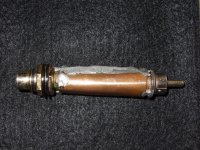
yes. you know about that problem but my shield does not look that bad !
") Nothing critical, just 2 resistors inside.
Nothing critical, just 2 resistors inside.i build the Hirage and i build it well. no cables in the signal pass. resistors from the local musicians shop so there is a change that the music has past at least one time though them. just kidding. actually it measured not that bad. bias is very stable and i was able to reduce input DC to a low and stable value. but oh boy, i can really improve technical performance with very little effort. amplification is huge with 38dB. that is really crazy and unecesarily amplifying noise and distortion. noise was at -135dB, not that bad considering the ample gain. distortion is second only, a lot of it and that was expected. it behaves totally monotonic so no hard clipping (overload was 150mV 1% distortion) and good low level performance ( 0.05% 2nd @10mV). at 50mV second harmonic was under 0.5%. that will not be audible as distorted but it will give some (welcome?) character. i could improve that to 0.015% just by adjusting the amplification to a more sane 26dB but i decided to listen first to the circuit "naked" to get an idea of the original intention. more pictures and measurements tomorrow.
i listened a bit to the Hiraga le pre-pre optime how i will call it and i was surprised. the sound is not bad at all. i had some terible hum problems but after substituting the RIAA stage and also grounding the RIAA stage it was gone. noise is low because the high gain alows for a very low volume setting of my preamp. i whould say it is some 3 dB worse then my MPP but that is still very good. the soundstage was somehow bigger, more up front and more difuse that i am used to but the music was intact. no spittyness, no nasties. in terms of speed and resolution it is no match to my Goldstandart and tonal palette is not as diferentiated as my MPP low Z but that did not distract from the enjoyment. i can now better understand why it is so popular with DIYers and it also reminds me on my first contact in the early 80th. it can be build in some hours and works right away. OK, i took some provision for succes in matching the transistors for Hfe. i took the better ones for the active devices and the lower grades for the current mirror and found 4 in 5 that matched, no pain at all. i trimed DC offset at the input with a resistor after i have found the right value with a trimmer. it was simply a 33kOhm on top of the resistor to the positive supply so i did not trim the current mirrors like Hirage. i have some trouble with the high gain in my system and could not advance the volume to more the 20 on my display. i usually listen at 40 so i will rebuild the Hiraga for less gain with the advantage of lower distortion and lower output impedance. i have also other interesting ideas that could help your version to sound better and better match your system. if all is ready and well i plan a small run for sales. Although not worldclass any more it is the most afordable way to high end nirvana i know.
today i cut the output impedance, the gain and distortion in half and raised the upper frequency limit to double the original value (have you seen Walk Hard ?) and now we talk business. the sound improved at lot and the gain is now in a comfortable range. it is no more diffuse and much more extended in the treble. i came up with a weighting scale to describe better what i am hearing. i came up with a scale from 50 to 100. 50 is average, 60 is good, 70 is satisfying, 80 is very good, 90 is excellent, magic, 100 is perfect, hand of god, paradise, satori, state of bliss. so the Hiraga 2.0 scored 85 after modification and advanced to 90 during the next hour of listening. to put it in perspective i would give the MPP Low Z 93 and the Goldstandart 96. it crossed the border of magic and that does not happen often at chateau Gerhard. i also came up with some additional descriptions to put everything more in perspective. PH : philosophical design, changes the way we think about circuits, PSY : psychological design, changes the way we listen, TA : technical advantage, measures sate of the art, is ether very pretty build and compact or battleship luxury, shows new circuitry with a genuine advantage like lower distortion and wider bandwidth. BC : budget champion, very good performance price ratio. so i would give the Hiraga 2.0 85-90 PH, BC and here is the circuit. i selected the active transistors to Hfe 240 and the current mirror to 210 similar in both channels.
Attachments
can that circuit be improved without destroying the PH quality of extreme simplicity of the signal path ? you bet, and i will try them all. first is the Cagomat version with low pass filtering of the current mirror. Cagomat uses a 200uF capacitor that i will try but i think it´s to small for optimum suppression in the lower reaches so i will try up to 2200uF several types here. second is an improved current mirror and third is substituting the bias resistors with constant current sources of various designs. here the simple Fet solution is shown. Fet cascodes or LED bias could be used for even stiffer regulation. i have seen so many biasing arrangements in my life that i came to the conclusion that it must be a major problem for some.
of cause you can combine all or leave out what you do not like. as simple as that circuit is, it has a lot of tweeking potential.
of cause you can combine all or leave out what you do not like. as simple as that circuit is, it has a lot of tweeking potential.
Attachments
hi salas. circuit in 355 is the one that i am using momentarily. it has 32dB of gain (still a lot but it sounds great) and i use a 5.5Ohm cartridge with 0.6mV output. i forgot to thank Christian of Music World in Brilon for the donation of the very nice sounding 1W metal film resistors.
Allen: the circuit is theoretical. to avoid thermal drift i would search for fets that need around 0.65 volts of gate voltage and produce 2mA. then i would thermocouple both. at that voltage temperature dependence of fets is near zero. i am really surprised that you come up with that kind of questions. don´t you know that i have studied with some really extraordinary people and that kind of problems are so easy to solve it is a joke ?what do you think about a servo to keep the current stable? give me any complicated circuit to analyse and i make it even more complicated. simply enjoy what i am doing here. it´s a gift to the DIY society. malkolm always said to me : "you crack every code"
Allen: the circuit is theoretical. to avoid thermal drift i would search for fets that need around 0.65 volts of gate voltage and produce 2mA. then i would thermocouple both. at that voltage temperature dependence of fets is near zero. i am really surprised that you come up with that kind of questions. don´t you know that i have studied with some really extraordinary people and that kind of problems are so easy to solve it is a joke ?what do you think about a servo to keep the current stable? give me any complicated circuit to analyse and i make it even more complicated. simply enjoy what i am doing here. it´s a gift to the DIY society. malkolm always said to me : "you crack every code"