i have not much choice in the MPP and need LEDs that work with low voltage to light up. red and infrared have the lowest zener voltage. dc impedance is the same as a resistor with the same current draw under the same voltage conditions. i do not know how that impedance changes over frequency but somehow a led looks like a vacuum cap to me or what is inside a led ? i will look it up.
Joachim just use what led you got, only bypass it well. After bypass, small change stuff so to spend enough time for now there IMHO. Maybe you will need a 100R resistor towards the Vref's client node so to form RC if the impedance is small for a sane value cap to bypass well. Lets tie it to PSU instead of ground so for the cascode base not to pick up stuff from ground, like Werner said?
i looked at your input stage again and it is all there to behold. what looks very basic on the surface has a great desire to sound atractive. we listened today very carefully to the Diy version of the MPP head amp compared to the lab sample of my goldstandart. it is hard to surpass the haevily fedback goldstandart in terms of low distortion, extention and speed but the lower hiss was obvious although we had a problem with hum that came from the arm prototype with no groundwire at that moment. the goldstandart beeing balanced ( i still call it pseudobalanced, so please forgive me dear reader that i am so stubburn, i know there ain't no signal flowing in the midle theroretically but i spare you my thoughts on balanced for the moment) had no problem with the missing groundwire beeing silent in the humm bussyness. what the MPP could was sounding very human in the midrange but it shurely needs tighter regulation that comes as a bonus in the goldstandart because of topology. so i will more focus on unbalanced and try to tighten up the soumd to be more precise. that circuit in it's naked form has no tendency to jell at you and is rather forgiving on flaws. a bit to much for me, enjoying a faster ride.
it could have done great in brittain in the 60th and 70th.
it could have done great in brittain in the 60th and 70th.
i have now the measurements on the Accuphase C27 on hand made by the Test Factory, a certified lab. the sales blurb says : S/N Ratio MC 60dB = 98dB and S/N Ratio MC 70dB = 90dB. the "real" measuments where : S/N Ratio @ 0,5mV, 20 Ohm =81,5 dB what is still impressive, the output is esentially distortion free with the noiseline starting at 20Hz with -108dB showing the typical RIAA shape improving to -145dB at 20kHz. this the resullt of massive paralleling, no less then 8 parallel symmetric diferential stages with 32 bipolar transistors in the MC input stage. RIAA is correct what looks like +- 0.2dB up to higher than 100kHz on the quite compressed thumbnail plot. so happy paralleling, it seems that the Accuphase people got it working without stability, noise and dsitortion probems over a very wide bandwidth.

distortion problems, i suffer from them when i type to quick

i am back in germany, so sorry john that we could not meet but i come more often.
today i iserted LEDs instead of the 220 Ohm bias resistors (until now without low pass).
i measured 1.9V across the 220 Ohm resistors so i choose red LEDs that light up at 1.7V.
one very positive result was that DC offset came down from over 100mV to under 15mV, so i am shure, that after trimmimg the input stage i can DC couple to the servoed second stage. tomorrow i will add the low pass and look at PSSR.
here is a link for you Salas :KurzweilAI.net
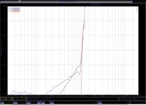
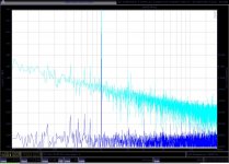
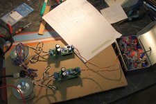
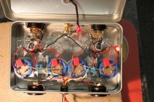
yesterday i have finished the LED bias version of the MPP and must say that i am very pleased with the result. bias in the cascode stage is now very stable and similiar in both channels. i got 10dB less noise (sorry, no 30dB improvement, regulation was already to good) under 1kHz now lying at -130dB and less hum. a added two pot meters for DC bias trimming. i got it better then +-5mV and quite stable so DC coupling to the RIAA stage is possible. later i substituted the pots with fixed resistors. distortion is now under -110dB at 50mV out, mostly second harmonic. one channel did 4dB better in second and a bit worse in third, being also some 0.4dB louder. that can be zerroed in with R1 and R3 but i left it that way. i will post the measurements of both channels paisted on top of each other and also a look at the physical circuitry. i think the circuit can not be improved much any more without bigger topological changes. bias to the input stage could be anhanced with constant current sources and improved current mirrors but regulation and stability is already very good. the bases of the cascode transistors could be tied to the current mirror of the input stage but i like my design better because it allows for independent optimisation. i would call that the definitive DIY version now. it uses no exotic parts not counting the input transistors that can be substituted with other typed i have described here. i will give it a listen today and also build the matchng RIAA stage.
Attachments
i also like to tell you about the noise performance. noise density is around 0.5nVqHz comparable with a ca.12Ohm resistor and some 6dB better then a low noise OPA. it can be improved by 3dB if you shunt the current mirrors with a 2200uF capacitor. i would recommend Pannasonic FM or Rubicom ZLH for maximum dynamics and resolution or Nichicon Muse or Elna Silmic for a somewhat rounder tone. other mothers have nice daughters too, so there is a dazzling choice of other subtitudes and i have not tried everything. this is one of the nice things with DIY, you can choose your own components.
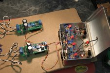
today i finished the RIAA stage and it worked right away. i used "the best sounding integrated OP amp" LT1028 just for fun and because i had i lying around. it works here with a source impedance of 340 Ohm because it has quite low current noise for a bipolar that is optimised for voltage noise. my default choice whould be the LT1468 or OPA827.
but anything could be used here and if you want to bargain hard even a NE5534 that i see recently more often to my surprise in very expensive high end equipment. but first i tried the MPP LED with my reference MM phonostage, a quite sofisticated 3 stage design with two active gain stages and a buffer. what struck me most was that the tired treble had totally gone, replaced by a very open, high speed sound. it was as if the soundstage had been lit up by a light. hum was non existing, ear close at the speakers at high volume. hiss had a very faint "light" character (ear at speaker) absolutely inaudible at the listening seat at quite advanced volume, certainly in the neiborhood complaining class. the sound was a bit more spacy then focussed, this a function of the small and wide radiating mini monitors i am currently using. soundstage was like sitting at the boundary of a quarter sphere looking at the inside so some sounds seemed to come from left and right closer to the ears then to the speakers. the speakers where not audible as sources. after 3 records i thought the bass was a little light and raised the level of my subwoofer some 1 - 2dD. that solved that issue. i know the effect quite well from tightly regulated circuits and are used to adjust acordingly.
after work i tried the fitting RIAA stage. i had at that point removed the coupling capacitor. DC coupling is posible when i closed the metal box, DC max is under 3mV in that case. in "open air" the current fluctuations in the input stage are too fast to be captured by the servo so 50mV max can happen. The sound with the fitting RIAA was a bit softer then with my reference MM stage but also a bit more focussed. in my experience that can come from the removed coupling capacitor that can give the impression of fals detail. my favorite choise RifaPHE450 with Röderstein/Vishey MKP bypass errs a bit in that direction and gives great speed, rythm and pace on pop and rock. listening to the art ensemble of chicago all the bells and wistles where there in micro detail. where i got a real culture shock was on Nina Simone Sings the Blues, a recording that can sound brittle and fatiquing. not so this time. the sound transfered me magically into the studio. this is a great phonostage for blues and jazz from the 50th and 70th.
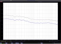
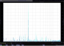
here come some measurements that i did today. first is RIAA curve. the shape of the RIAA curve is absolutely similar on all channels accurate to +- 0.3dB with a slightly falling characteristic the way i like it. my Titan has about 2dB gain on top of 8kHz so in my system there will be no shortage of treble for greater accuracy the circuit can be easily tuned. it is just 2 capacitors and two resistors. 1% accurate parts are sufficient because modern parts have often better tolerance then advertised. as i said one channel is 0.4 dB louder but the shape of the RIAA is absolutely the same. no problem in my sytem because it "hangs" a bit to the left because of slightly asymetric acoustics. i used to control that with the balance knob and the MPP had good symmetry of the soundstage in my system. anyway, gain can be trimmed the way i was talking about. the Neumann constant can be added with a 15 Ohm resistor in series with the 0.22uF RIAA cap. i am not a big fan of that and there is an interesting survey of that issue on the Stereophile website. Keith Howard has looked in that glas much deeper then me. overload was at 12V RMS (33,6V P-P) with +-15 V on the opamps and +-13V on the input stage.