Is R7 in the right place?here is one way to implement inductive RIAA into the MPP structure. i have not build it yet so take the values with a grain of salt.
I put some thoughts into this Fet constant current source. The device i have chosen has very high (40mA) IDss and i pad it down to 8mA so regulation is good. the circuit as is is dead quite (very low hum and hiss, no HF) but for the perfectionist regulation can be improved. one possibility is a fet cascode but that is only good to 3mA or so. want can be implemented is a mos-fet cascode that has some higher current. also bias to the folded cascode can be low pass filtered because it does not need much base current. see the improved schematic. the mos-fet section is not dimensioned yet. i have to search for the right parts. i am also working on the high Z (Fet-input) version of the MPP after Scott Wurzer gave me some advice about trimming. maybe i only trim for lowest distortion and do the DC offset cancelation with a servo. anyway, this develops nicely and new ideas are coming in all the time.
Attachments
Cascode is better theoretically. Also a single RF jfet can make do extending its CCS impedance frequency wise if you will follow the minimal path. All those alternatives you do check out by listening to point to point prototypes anyway, so you will know the proof and the pudding thing soon so to say.
shure, a BF862 praised so much here could do the job quite well. i would select it for highest (and matching) IDss because it can be as low as 10mA (a little low, but still would work) and as high as 25mA, i use 8mA idle here and found it sounded a bit better then the initial value ( that was lower) i had used. Somehow cleaner and more transparent. but i will decide on that later and let other people hear too.
also bias to the folded cascode can be low pass filtered because it does not need much base current.
Surely the PSRR improves when you tie the filter capacitors to the supply as opposed to the ground. With the folded cascode transistors' bases grounded through these caps any variation on the supply lines makes it straight through to the output of the amplifier.
Hello Werner
Did you ever try a dedicated Vref for the cascode BJT's base than the resistor divider (R11,R5) off main psu? Is this a solution you ended up after some subjective comparisons? I ask because I remember your CCT from an old thread and maybe you had done several things till then. I am also fan of your online cart reviews and rake angle articles. The only ones relatively recent in time explaining and testing some crucial hands on parameters beyond blah blah. Do you still write reviews?
Did you ever try a dedicated Vref for the cascode BJT's base than the resistor divider (R11,R5) off main psu? Is this a solution you ended up after some subjective comparisons? I ask because I remember your CCT from an old thread and maybe you had done several things till then. I am also fan of your online cart reviews and rake angle articles. The only ones relatively recent in time explaining and testing some crucial hands on parameters beyond blah blah. Do you still write reviews?
Did you ever try a dedicated Vref for the cascode BJT's base than the resistor divider (R11,R5) off main psu?
No. I'm afraid I can devote very little time to DIY audio, or even listening. In the past this led to analysis paralysis, with me just simulating tens of alternatives and building nothing. Nowadays confine myself to simple circuits, almost zero analysis, but at least I build one once in a while.
You may remember that Jonathan Carr has the habit of giving each cascode transistor its very own regulated supply. But on the other hand, something august like the Vendetta has just a resistive divider there. So both options can be made to sound good.
Do you still write reviews?
Thanks for the kind words. Officially yes, but in practice I very very seldomly come to reviewing anything.
you recommend that i tie the capacitors to the supplies as in the following schematic
See above. But it is a fact that the caps tied to V++ give you ~30dB more PSRR at 100Hz, rising with frequency.
werner, i looked up older elektor designs, and yes, the caps are tied to the supply !
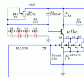
looking at an old circuit (the elektor preamp with MAT02/MAT03) i remembered that we used LEDs as low noise voltage references in the old times. i can not remember which ones had the lowest noise. we used red ones because they were the only ones awailable at that time. i implemented that idea into the MPP and added a resistor in series with the bias fet to reduce capacitive loading. actually in one of my commercial designs i use that capacitance to optimise square wave response so this "flaw" came in handy. in our times i may try the new ultraviolet ones because they are so pretty.
looking at an old circuit (the elektor preamp with MAT02/MAT03) i remembered that we used LEDs as low noise voltage references in the old times. i can not remember which ones had the lowest noise. we used red ones because they were the only ones awailable at that time. i implemented that idea into the MPP and added a resistor in series with the bias fet to reduce capacitive loading. actually in one of my commercial designs i use that capacitance to optimise square wave response so this "flaw" came in handy. in our times i may try the new ultraviolet ones because they are so pretty.
Attachments
i will more closely look at your thread but i have followed it when time allowed. i met today with a friend, Brian Daily who is an Intel engineer that works for me from time to time. he will do the layout of the PSU and the MPP in FET version. we choose black PCB material with gold plating, that looks quite tasty. i was surprised how ok the prices are on those boards. PCB making seems to be very competitive.
i will more closely look at your thread but i have followed it when time allowed.
No need go searching, its a long thread with much building, troubleshooting, and anecdotal stuff. Here it is.


