DF96---Each R8 = 46.8 ohms [Fluke 8800A]
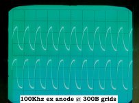
Have had to eat my words re the driver stage being flat out to 100khz, at the anode, yes, but not at the 300B grid.
Found a reasonably accurate True RMS AC voltmeter with a dB scale, and measured frequencies at -3dB,-6dB, and -12dB, at the R[choke loaded] and L[R loaded] 300B grids.
Right/Choke
-3dB 14,500
-6dB 26K
-12dB 51K
Left/Resistor
-3dB 27K
-6dB 46K
-12dB 82K
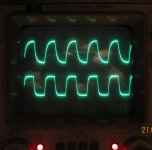
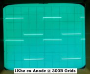
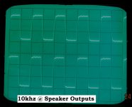
To complete comparisons, here is a scope pic of 10khz square waves, R/choke trace uppermost.
Lower trace is none too flash either, but the difference is graphic enough for this DIYer, and he'll be restoring the resistor status quo in his SE300B amp.
He can only envy the success of others using this technology.....
Have had to eat my words re the driver stage being flat out to 100khz, at the anode, yes, but not at the 300B grid.
Found a reasonably accurate True RMS AC voltmeter with a dB scale, and measured frequencies at -3dB,-6dB, and -12dB, at the R[choke loaded] and L[R loaded] 300B grids.
Right/Choke
-3dB 14,500
-6dB 26K
-12dB 51K
Left/Resistor
-3dB 27K
-6dB 46K
-12dB 82K
To complete comparisons, here is a scope pic of 10khz square waves, R/choke trace uppermost.
Lower trace is none too flash either, but the difference is graphic enough for this DIYer, and he'll be restoring the resistor status quo in his SE300B amp.
He can only envy the success of others using this technology.....
Attachments
Last edited:
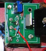
In the second wiring picture, is the black 9.1K resistor a stopper tied to grid? No other connection is visible on the tube socket.
The physical disposition is described in post #19.
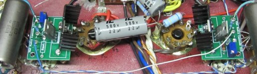
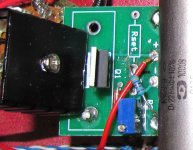
The first wiring pic is of the choke loaded scenario, and the resistor you observe, is a 9.1K Welwyn, a grid stopper indeed--not as close to the pin as ideally it should be, I know. The other socket connections going clockwise are the positive filament lead with 10R current sensor to ground,negative fil lead, and lastlythe plate-->OPT lead,brown,just seen beneath the socket. The second pic's of the resistor loaded scenario,only the stopper is a carbon film 10K resistor.
Hope this clarifies things....
I guess to be totally objective one should swap the sockets/scenarios over, and remeasure, and also check the LF response, though have no reason to doubt the latter. Maybe that WW grid stopper is not helping,but am now certain that choke in that layout is the problem.
Two things can be deduced from the measurements:
1. the choke is almost doubling the capacitance - not all that surprising.
2. the source has rather too high an output resistance, even though in theory it should have a rather low output resistance.
As its not the series resistor, it must be something related to the 'CCS'. Somehow that is not working, and instead of lowering the impedance below that of the bare triode-connected valve it seems to be raising it. Double check around there. Something is wrong.
Yikes! Here's my 10K square wave on the speaker terminals. Something else is wrong. I'd go with a 0.47uF cap to the choke. My 100 Hz square wave says that's all you need. Also if you are looking at the choke with the solder leads facing you I have the bias connected to the left lead and the cap and GM70 grid to the right lead. I don't know if that would make a difference.
Attachments
Two things can be deduced from the measurements:
1. the choke is almost doubling the capacitance - not all that surprising.
2. the source has rather too high an output resistance, even though in theory it should have a rather low output resistance.
As its not the series resistor, it must be something related to the 'CCS'. Somehow that is not working, and instead of lowering the impedance below that of the bare triode-connected valve it seems to be raising it. Double check around there. Something is wrong.
Thanks DF96 and Pieter.
Attached are pix of CCS before choke addition, and how they are now--first choke/R ch, then resistor/L ch.The latter have been mucked about by the changes,but I defy anybody to find a fault in their construction,how can one err with a pcb based item? It stretches credibility that one can be malfunctioning, now,with the choke, and the other not.If wanted, can do better detailed pix.
More interesting [? more relevant] are MelB's findings; his chokes are fed from the plate of his driver--surely much higher output impedance than the CCS mu output. Thanks MelB for the hints,might try them.
Perhaps the feed takeoff point should shift to the driver plate. Mu OP may be fine in theory, but not work so well in practice, though I had thought that question already answered, as riccoryder intimated earlier.
Again, thanks to all for their efforts on my behalf...
Attachments
I am not saying that the CCS fails with the choke, but works OK with the resistor. Your results seem to rule that out, as you have poor HF response in both cases.
Making a mistake in PCB-based construction is dead easy! Most of us on here will have done it. Pictures don't help me, because I have no idea what it is supposed to look like.
You need to measure the output impedance of the stage, as pieter t suggests. Alternatively, try taking output from the anode and measuring frequency response again.
Idea!
The B+ for your CCS driver tubes, is it coming off of the same cap?
Rephrase: What is the decoupling like between the right and left channel?
I say this as I'm looking at a 10k square wave on a line amp I built 10 years ago and it looks just like your bottom scope trace above. Now there is no way it should look like that in this line amp. I don't think, anyhow not according to the book it is in. (Except my right and left channel are NOT decoupled) I'm fixing that.
Just a thought!
Idea!
The B+ for your CCS driver tubes, is it coming off of the same cap?
Rephrase: What is the decoupling like between the right and left channel?
I say this as I'm looking at a 10k square wave on a line amp I built 10 years ago and it looks just like your bottom scope trace above. Now there is no way it should look like that in this line amp. I don't think, anyhow not according to the book it is in. (Except my right and left channel are NOT decoupled) I'm fixing that.
Just a thought!
Good thoughts, MelB!
Driver B+ comes off the same cap. How important is that? I thought decoupling only important between power and earlier stages, but open to correction, as it appears there is no decoupling between R and L channels at this, and 300B B+ takeoff point either. Good decoupling between driver and output B+ though.
Pieter t/DF96--measuring the output impedance may be easy for some, but not for me. How can the driver deliver a signal if unloaded? However, I'll have a go and report back. Your "appropriate formula" eludes me however--can you post it? I'll re-examine the CCS PCB with a fine tooth comb and remeasure FR with output from driver plates.
Pieter t/DF96--measuring the output impedance may be easy for some, but not for me. How can the driver deliver a signal if unloaded? However, I'll have a go and report back. Your "appropriate formula" eludes me however--can you post it? I'll re-examine the CCS PCB with a fine tooth comb and remeasure FR with output from driver plates.
Surprising that you can't find it yourself; a quick "google", and:
Measuring Input and Output Impedance
Grid choke query
I think the problem is solved.
The CCS survives triple scrutiny, the only anomaly is the pot has not been replaced with a fixed resistor.
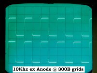
When anode is the output point, only minor differences between choke and resistor are seen, and pix demo the FR. Indeed, choke is better @ 100Hz and 1Khz, it's extra capacitance compromising performance at higher frequencies, as expected. BTW DF96--just how poor is poor HF? For Mu/R loading -6dB was 46K;anode/R loading, 88K. [Measured off 'scope as RMS ACVM not trusted]
The amp being needed, this exercise must stop--grid choke loading will be kept, as there is only a minor sacrifice at higher frequencies,but the mu output is set aside in favour of the anode. Sometime the pot will be replaced by a fixed resistor.
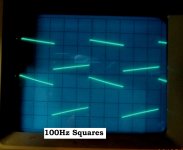
Most interesting to see other's scope pix--thanks MelB--how do you like my 100Hz squares? Maybe a larger value coupler is necessary....
Thank you all for your assistance,it's greatly appreciated, even if the output impedance measurement ended up in the too hard basket......
I think the problem is solved.
The CCS survives triple scrutiny, the only anomaly is the pot has not been replaced with a fixed resistor.
When anode is the output point, only minor differences between choke and resistor are seen, and pix demo the FR. Indeed, choke is better @ 100Hz and 1Khz, it's extra capacitance compromising performance at higher frequencies, as expected. BTW DF96--just how poor is poor HF? For Mu/R loading -6dB was 46K;anode/R loading, 88K. [Measured off 'scope as RMS ACVM not trusted]
The amp being needed, this exercise must stop--grid choke loading will be kept, as there is only a minor sacrifice at higher frequencies,but the mu output is set aside in favour of the anode. Sometime the pot will be replaced by a fixed resistor.
Most interesting to see other's scope pix--thanks MelB--how do you like my 100Hz squares? Maybe a larger value coupler is necessary....
Thank you all for your assistance,it's greatly appreciated, even if the output impedance measurement ended up in the too hard basket......
Attachments
Last edited:
Damn...and I was going to say put it on the anode too...
I spent a freekin' fortune for my .47uF coupling caps and now I need bigger ones? Thanks a lot!") I'll hook my scope up tomorrow and carefully run my low frequency, my signal generator only goes down to 20 Hz. I'll see if I detect any drop @ 20 Hz. My speakers drop off @ 30 Hz so....
I'll hook my scope up tomorrow and carefully run my low frequency, my signal generator only goes down to 20 Hz. I'll see if I detect any drop @ 20 Hz. My speakers drop off @ 30 Hz so....
But you should really notice a substantial difference in the sound between choke and resistor. Please let me know if you actually hear a difference. Do you still have the 640H ebay specials in there?
I spent a freekin' fortune for my .47uF coupling caps and now I need bigger ones? Thanks a lot!
I'll hook my scope up tomorrow and carefully run my low frequency, my signal generator only goes down to 20 Hz. I'll see if I detect any drop @ 20 Hz. My speakers drop off @ 30 Hz so....But you should really notice a substantial difference in the sound between choke and resistor. Please let me know if you actually hear a difference. Do you still have the 640H ebay specials in there?
Do you still have the 640H ebay specials in there?
Yes,for now, they're keepers.
Remember this amp is only driving 104dB efficient 500-5K E-horns, unlike your '70's, doing full range duty....but you never know--it could be asked to do that, so good LF response makes sense.
Cheers.
Just for kicks,you could try swapping the leads on the choke. It might change the freq response,if the choke has higher capacitance to ground (the core) on one end of the winding than it does on the other. (usually the case.) Though,with a high inter-winding capacitance,this effect might be swamped out?
I dunno,just a random thought.
I dunno,just a random thought.
The 'appropriate formula' for measuring source impedance is that for any potential divider: Vout=Vsrc x R1/(R1+R2). R1 is load. R2 is source impedance.
I am not familiar with the double FET CCS you are using, so I can't comment on whether the 'mu point' should give a really low impedance like a normal single device circuit. In your case it clearly isn't. Whether this is a fault or a design flaw is something which perhaps others can comment on. Don't assume that the original author of your circuit understood it properly, any more than you should believe everything you hear in a bar.
I am not familiar with the double FET CCS you are using, so I can't comment on whether the 'mu point' should give a really low impedance like a normal single device circuit. In your case it clearly isn't. Whether this is a fault or a design flaw is something which perhaps others can comment on. Don't assume that the original author of your circuit understood it properly, any more than you should believe everything you hear in a bar.
Just for kicks,you could try swapping the leads on the choke. It might change the freq response,if the choke has higher capacitance to ground (the core) on one end of the winding than it does on the other. (usually the case.) Though,with a high inter-winding capacitance,this effect might be swamped out?
I dunno,just a random thought.
A pretty good thought, which MelB raised earlier. Will try and measure the core-to-terminal capacitances, reluctant to disconnect/fiddle, having got it going well.... definitely better "distortion-free" power output, 8W clean, 10W early clip,12W useable "overhead." Want to get it back into service....
- Status
- This old topic is closed. If you want to reopen this topic, contact a moderator using the "Report Post" button.
- Home
- Amplifiers
- Tubes / Valves
- Most odd grid choke behaviour.