I have a most puzzling phenomenon I hope someone can explain.
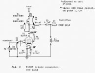
The amp is a fixed bias SE300B, driven by triode-connected CCS loaded E180F, as per the Audioroundtable thread. Re: 300B SE Project, Part 9 - E180F, E280F, D3a pentodes - triode connected
Initially, not having grid chokes I departed a little from the schematic--mu output from CCS into 0.22uF coupling cap into 100K grid R. Perfectly satisfactory performance, on bench and sonically,driving just an Edgarhorn.
But the urge to try a grid choke was spurred on by the 640H eBay item, and good reports thereof, elsewhere on this forum.
However,their installation [plus 1uF coupler] had dramatic and unexpected impact on HF response, with rolloff beginning 3dB down at 10K,-6dB at 20K. Previous figures, -3dB 53K,-6dB at 100K. Checking with scope probe at E180F plate, all as before,from mu out,as above. Inserting 91K below the choke made little difference.
Restoring the cap/resistor restored the HF, and a decent 1K square wave....
Maybe the choke size is insufficient,[the original being 1700H], though others seem happy with it.
Does anyone have a simple explanation of this puzzle? It's got me beat.
The amp is a fixed bias SE300B, driven by triode-connected CCS loaded E180F, as per the Audioroundtable thread. Re: 300B SE Project, Part 9 - E180F, E280F, D3a pentodes - triode connected
An externally hosted image should be here but it was not working when we last tested it.
I hope others can open these images, I cannot. There is no other way of downloading an image it appears. Initially, not having grid chokes I departed a little from the schematic--mu output from CCS into 0.22uF coupling cap into 100K grid R. Perfectly satisfactory performance, on bench and sonically,driving just an Edgarhorn.
But the urge to try a grid choke was spurred on by the 640H eBay item, and good reports thereof, elsewhere on this forum.
However,their installation [plus 1uF coupler] had dramatic and unexpected impact on HF response, with rolloff beginning 3dB down at 10K,-6dB at 20K. Previous figures, -3dB 53K,-6dB at 100K. Checking with scope probe at E180F plate, all as before,from mu out,as above. Inserting 91K below the choke made little difference.
Restoring the cap/resistor restored the HF, and a decent 1K square wave....
Maybe the choke size is insufficient,[the original being 1700H], though others seem happy with it.
Does anyone have a simple explanation of this puzzle? It's got me beat.
Last edited:
Thank you.
Wondered if taking the signal from the mu output is the problem, but can't see why. You're saying an 8000H choke wouldn't help? By the way, LF rolloff doesn't seem to be a problem. This mod seemed logical, after "purifying" filament supplies with a Coleman kit.....
Thanks again.
Wondered if taking the signal from the mu output is the problem, but can't see why. You're saying an 8000H choke wouldn't help? By the way, LF rolloff doesn't seem to be a problem. This mod seemed logical, after "purifying" filament supplies with a Coleman kit.....
Thanks again.
To wind a high inductance choke with low capacitance is not easy. However, you said you also tried a 91k resistor in series (below?) the choke and that didn't help. If the resistor went from choke to ground and made little difference this suggests that the choke, or something else, has high capacitance to ground or that the previous stage has high output resistance. Did you try adding the 91k 'above' the choke too? Does the 1uF coupling cap have high stray capacitance to ground? Did you accidentally disconnect the E180F triode connection?
I used those same grid chokes in both my Parallel 300B amps and my GM70 amps with no problems at all. Testing my GM70 at 18k it is starting to drop off but I was blaming that on the Hammond output transformer. I guess it could be the grid choke??? I am using .47uF coupling caps only. I would think you could go even lower with no problem. Trying knocking that down I would be very interested in what happens. How much current is running through your E180F?
Also I emailed the guy that is winding them as I was concerned I might "burn one out" going full drive on my GM70. He says there is no chance of that but I am probably saturating them for sure with anything over 1 mA. In listening tests I do not hear any ill effects at very very loud levels. And oh yes they do make a huge difference in the sound. You can apply all the theory you want to that vs. a resistor but the results with these things are quite remarkable. I would go so far as to say best upgrade I've ever done.
Also I emailed the guy that is winding them as I was concerned I might "burn one out" going full drive on my GM70. He says there is no chance of that but I am probably saturating them for sure with anything over 1 mA. In listening tests I do not hear any ill effects at very very loud levels. And oh yes they do make a huge difference in the sound. You can apply all the theory you want to that vs. a resistor but the results with these things are quite remarkable. I would go so far as to say best upgrade I've ever done.
I should probably add the guy did say they are meant for small signal tubes and not large triodes.
I originally got these things as I'm using fixed Bias in my parallel 300B amps so was using them as a way to lessen the chance of a tube running away (lower grid resistance) I built these amps 8 years ago and have run through two sets of 300B's. My experience with the 300B's is by the time they are beginning to run away they are done anyhow. There is nothing left in there filaments. By the time one of them starts to run away testing the group of four tubes on my Hickok tester where I drop the filament voltage from 5 to 4 volts and watch the needle will drop like a rock. A new tube dropping the voltage from 5 to 4 volts the needle does not move.
So using them to stabilize your bias is really moot. If that is what you are using them for? I would guesstimate I am getting about 4000 hours out of my 300B's (Chinese) and 4 out of 4 aged pretty much the same two times now.
Most odd grid choke behaviour
Thanks for the assistance....
No, did not try 91k above choke--maybe I should. Thought choke had to be close to the grid....
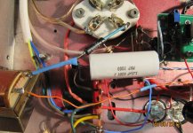
If I could download a photo of the cap's location, I would, but it appears DIYAudio needs an URL, and all my images are on the PC,not cyberspace. Best described as very much suspended in free air....the chokes are attached to chassis wall 50-60mm from the pin,means a long grid stopper--9.1k Welwyn--and even longer space for cap to bridge from CCS to choke. Don't know if that answers your question re stray capacitance to ground...
No, no accidental disconnections.
To wind a high inductance choke with low capacitance is not easy. However, you said you also tried a 91k resistor in series (below?) the choke and that didn't help. If the resistor went from choke to ground and made little difference this suggests that the choke, or something else, has high capacitance to ground or that the previous stage has high output resistance. Did you try adding the 91k 'above' the choke too? Does the 1uF coupling cap have high stray capacitance to ground? Did you accidentally disconnect the E180F triode connection?
Thanks for the assistance....
No, did not try 91k above choke--maybe I should. Thought choke had to be close to the grid....
If I could download a photo of the cap's location, I would, but it appears DIYAudio needs an URL, and all my images are on the PC,not cyberspace. Best described as very much suspended in free air....the chokes are attached to chassis wall 50-60mm from the pin,means a long grid stopper--9.1k Welwyn--and even longer space for cap to bridge from CCS to choke. Don't know if that answers your question re stray capacitance to ground...
No, no accidental disconnections.
Most odd grid choke behaviour
Thanks for your assistance. Did wonder how your frequency testing came out...
As per the circuit design, the E180F's pass exactly 11mA. But I take the output from the CCS' mu point, for lowest output impedance, rather than the E180F plate. Maybe the choke doesn't like that. Your GM70 amp I note the output is from the 7027's plate.Your 0.47uF coupler is quite small, cf 4.7uF for a 1700H L in the original circuit, yet your bass is unaffected. One would have predicted some rolloff, but apparently not in practice.
In my application, only driving mid-range, it could be argued one is being unduly fussy, but I figure one should always go for max extension possible, for best fidelity, besides may one day be asked to drive a full ranger....
Cheers and thanks again.
I used those same grid chokes in both my Parallel 300B amps and my GM70 amps with no problems at all. Testing my GM70 at 18k it is starting to drop off but I was blaming that on the Hammond output transformer. I guess it could be the grid choke??? I am using .47uF coupling caps only. I would think you could go even lower with no problem. Trying knocking that down I would be very interested in what happens. How much current is running through your E180F?
In listening tests I do not hear any ill effects at very very loud levels. And oh yes they do make a huge difference in the sound. You can apply all the theory you want to that vs. a resistor but the results with these things are quite remarkable. I would go so far as to say best upgrade I've ever done.
Thanks for your assistance. Did wonder how your frequency testing came out...
As per the circuit design, the E180F's pass exactly 11mA. But I take the output from the CCS' mu point, for lowest output impedance, rather than the E180F plate. Maybe the choke doesn't like that. Your GM70 amp I note the output is from the 7027's plate.Your 0.47uF coupler is quite small, cf 4.7uF for a 1700H L in the original circuit, yet your bass is unaffected. One would have predicted some rolloff, but apparently not in practice.
In my application, only driving mid-range, it could be argued one is being unduly fussy, but I figure one should always go for max extension possible, for best fidelity, besides may one day be asked to drive a full ranger....
Cheers and thanks again.
Most odd grid choke behaviour
DF96--thanks for the input--I've yet to master uploading pix but the schematic is in the link in the first post-- click "Open link in a new tab" and the entire article on trioded E180F etc [in audioroundtable.com] is there.
Using the "mu" output and CR coupling the performance is exemplary. It's only when the choke is subbed the highs die.
The driver has very low output impedance. The choke provides a low impedance to d.c. (otherwise lost due to the cap) to prevent the bias from shifting (causing blocking distortion etc), when the drive level is high enough for the positive peaks to drive grid current. The design with the choke supports class-2 operation.
Simply using a resistor in place of the choke, or adding the significant series resistance mentioned to the choke, will reduce available output power to class-1 levels and may give the amp a less desirable overload characteristic. Performance is not impaired while below the reduced power limit though.
I'd consider an alternate approach to the choke, adding a mosfet follower after a high-value resistor where the choke is now (gate coupling cap reduced to a normal size, .1 or so etc), and directly (no cap) driving the grid from the source. If needed, adjustable bias could be applied to the bottom side of the gate resistor. I realize it looks redundant to add a follower after a stage that's already low-impedance output, but it's needed for d.c. characteristics. Although the driver load might be simplified, what's there now should have good supply noise immunity and low distortion.
The pull-down resistor or current source on the follower source need not operate at as much current as the peak available drive current, but it should at least be sufficient to maintain a good negative-going slew rate into the output stage capacitance.
If the capacitance in the driver plate circuit is rolling off the high-end response excessively, short of using different fets, adding a high value load resistor from the plate to ground is an easy way to broaden the bandwidth some. (adjust active load to provide additional current if needed to maintain the operating point) A resistor to the supply would do the same thing, but that location would degrade PS noise immunity.
If there's no global NFB, bandwidth covering the audio range is sufficient, but otherwise the driver should have enough bandwidth and slew rate to pass the out of band harmonics introduced to earlier stages by the feedback signal. If the bandwidth is insufficient for the feedback spectrum to pass all the way to the output stage to cancel most of the distortion generated there, driver non-linearity may produce additional higher order intermodulation products (three times one signal minus double another etc). Any frequency compensation or rolloff added should ideally be before the first stage having significant distortion, or feedback may increase generation of those higher-order (more offensive) distortion products.
Last edited:
Thanks for the assistance....
If I could download a photo of the cap's location, I would, but it appears DIYAudio needs an URL, and all my images are on the PC,not cyberspace. Best described as very much suspended in free air....the chokes are attached to chassis wall 50-60mm from the pin,means a long grid stopper--9.1k Welwyn--and even longer space for cap to bridge from CCS to choke. Don't know if that answers your question re stray capacitance to ground...
When you're composing a new post, make sure you've chosen the "Go Advanced" option. That's the button to the lower right in "Quick Reply."
Once you're on the "Reply To Thread" page, you'll see a toolbar. In the top row of tool buttons, there's a "paper clip" icon (to "Attach" a file to your post). Click on that and a new "Manage Attachments" window should pop up. In that, click on Choose File, find the file on your PC, select it, click Upload. Then you can close the Manage Attachments window and the picture file should be attached to your post.
I hope that helps.
--
Most odd grid choke behaviour
Hi DF96, thanks for your persistence.
CCS's are on proprietary PCBs from K&K, and behave as they should--perfectly--as long as they are loaded by an R and not an L, hence the puzzlement. I'll try to load a pic.
I think Miles Prower has the right idea--forget about the choke, and revert to the good ole reliable resistor...still doesn't explain why others use them to advantage and without bother.
OK. There must be something wrong with your 'CCS'. The choke will have much higher stray capacitance to ground than a resistor. One of the FETs faulty, or miswired?
Hi DF96, thanks for your persistence.
CCS's are on proprietary PCBs from K&K, and behave as they should--perfectly--as long as they are loaded by an R and not an L, hence the puzzlement. I'll try to load a pic.
I think Miles Prower has the right idea--forget about the choke, and revert to the good ole reliable resistor...still doesn't explain why others use them to advantage and without bother.
Most odd grid choke behaviour
Thank you sir for your exhaustive examination of the problem. I fear much of it is over my aging and addled head,tho do understand mosfet followers, and Class A2 operation,just never had the cohones to do it. But I'm not after power here--just purity.
To clarify one point--frequency response at the driver plate is more or less flat, out to 100khz. It is similar at the 300B grid, if R loaded.
The answer has to be that, as earlier noted,and I quote M.Prower: "The problem is likely stray capacitance of the grid choke that's bypassing the high frequencies," and DF96: "To wind a high inductance choke with low capacitance is not easy." all occurring in the particular layout of this amp. I'll try for pix to show before and after....
Thanks to all for your inputs....
The driver has very low output impedance. The choke provides a low impedance to d.c. (otherwise lost due to the cap) to prevent the bias from shifting (causing blocking distortion etc), when the drive level is high enough for the positive peaks to drive grid current. The design with the choke supports class-2 operation.
Simply using a resistor in place of the choke, or adding the significant series resistance mentioned to the choke, will reduce available output power to class-1 levels and may give the amp a less desirable overload characteristic. Performance is not impaired while below the reduced power limit though.
I'd consider an alternate approach to the choke, adding a mosfet follower after a high-value resistor where the choke is now (gate coupling cap reduced to a normal size, .1 or so etc), and directly (no cap) driving the grid from the source. If needed, adjustable bias could be applied to the bottom side of the gate resistor. I realize it looks redundant to add a follower after a stage that's already low-impedance output, but it's needed for d.c. characteristics. Although the driver load might be simplified, what's there now should have good supply noise immunity and low distortion.
The pull-down resistor or current source on the follower source need not operate at as much current as the peak available drive current, but it should at least be sufficient to maintain a good negative-going slew rate into the output stage capacitance.
If the capacitance in the driver plate circuit is rolling off the high-end response excessively, short of using different fets, adding a high value load resistor from the plate to ground is an easy way to broaden the bandwidth some. (adjust active load to provide additional current if needed to maintain the operating point) A resistor to the supply would do the same thing, but that location would degrade PS noise immunity.
If there's no global NFB, bandwidth covering the audio range is sufficient, but otherwise the driver should have enough bandwidth and slew rate to pass the out of band harmonics introduced to earlier stages by the feedback signal. If the bandwidth is insufficient for the feedback spectrum to pass all the way to the output stage to cancel most of the distortion generated there, driver non-linearity may produce additional higher order intermodulation products (three times one signal minus double another etc). Any frequency compensation or rolloff added should ideally be before the first stage having significant distortion, or feedback may increase generation of those higher-order (more offensive) distortion products.
Thank you sir for your exhaustive examination of the problem. I fear much of it is over my aging and addled head,tho do understand mosfet followers, and Class A2 operation,just never had the cohones to do it. But I'm not after power here--just purity.
To clarify one point--frequency response at the driver plate is more or less flat, out to 100khz. It is similar at the 300B grid, if R loaded.
The answer has to be that, as earlier noted,and I quote M.Prower: "The problem is likely stray capacitance of the grid choke that's bypassing the high frequencies," and DF96: "To wind a high inductance choke with low capacitance is not easy." all occurring in the particular layout of this amp. I'll try for pix to show before and after....
Thanks to all for your inputs....
I should probably add the guy did say they are meant for small signal tubes and not large triodes.
I originally got these things as I'm using fixed Bias in my parallel 300B amps so was using them as a way to lessen the chance of a tube running away (lower grid resistance) I built these amps 8 years ago and have run through two sets of 300B's. My experience with the 300B's is by the time they are beginning to run away they are done anyhow. There is nothing left in there filaments. By the time one of them starts to run away testing the group of four tubes on my Hickok tester where I drop the filament voltage from 5 to 4 volts and watch the needle will drop like a rock. A new tube dropping the voltage from 5 to 4 volts the needle does not move.
So using them to stabilize your bias is really moot. If that is what you are using them for? I would guesstimate I am getting about 4000 hours out of my 300B's (Chinese) and 4 out of 4 aged pretty much the same two times now.
MelB--overlooked your question, sorry--no, not using them to stabilize bias,which seems rock steady--I was just interested to see if I could improve my amp's performance, and enjoy the enhancements you reported....
Cheers.
Grid choke queries
Apologies for the lateness of these images, but better late than never.
Since asking the question, increasing trouble with instrument gremlins leads to serious doubts whether the observed HF roll-off is as severe as thought.
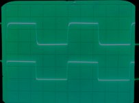
To demonstrate possible differences, have wired the right channel with the choke load and the left channel with resistor load. The 'scope pic shows 1khz square waves, upper trace right channel, lower trace the left. The slight degradation of the square wave in the upper trace suggests high frequency loss, presumably via the grid choke's capacitance, as others have intimated.
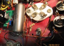
Have also attached the schematic, tho the 1700H choke is replaced by the eBay "special"--640H, and coupling cap is 1uF cf 4.7uF, and pix to show the layout.
Many thanks again for the help in posting images.")
Apologies for the lateness of these images, but better late than never.
Since asking the question, increasing trouble with instrument gremlins leads to serious doubts whether the observed HF roll-off is as severe as thought.
To demonstrate possible differences, have wired the right channel with the choke load and the left channel with resistor load. The 'scope pic shows 1khz square waves, upper trace right channel, lower trace the left. The slight degradation of the square wave in the upper trace suggests high frequency loss, presumably via the grid choke's capacitance, as others have intimated.
Have also attached the schematic, tho the 1700H choke is replaced by the eBay "special"--640H, and coupling cap is 1uF cf 4.7uF, and pix to show the layout.
Many thanks again for the help in posting images.
Attachments
- Status
- This old topic is closed. If you want to reopen this topic, contact a moderator using the "Report Post" button.
- Home
- Amplifiers
- Tubes / Valves
- Most odd grid choke behaviour.