Hey Globu..,
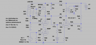
Forget about the UL thingy in the cascode in this case. It lowers Zout and we want the highest possible to make the driver work as close to a currentsource as possible. But 6N6 will surely work OK in cascode.
This is how I would do it.
You can consider the Schade Zout is in the ballpark of the same tube triode-strapped.
As Waveborn says you can also use a low Ri triode but then you must add a series resistor as in one my examples above. Its the one with 6C45 driver.
Attachments
Last edited:
Ok - so the schade mixes in with the driver output impedance so I see that has to be constant to do that. I agree that GNFB is no good, do you know how much schade feedback changes the output impedance of the pentode? Is it lower than triode strapped?
Can be way lower than triode-strapped.
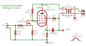
The output impedance (effective plate resistance) will depend on the amount of feedback. The lowest achievable Rp is using 100% feedback, such as with a pentode driver loaded by the feedback resistor, and is approximately 1/gm.
I have a 6L6 SE amp on the bench with 100% feedback that has a measured (dynamic) effective plate resistance of about 200 ohms. Quite nice in SE mode, I'm getting full power bandwidth to 25 Hz using an inexpensive OPT.
This amp makes about 9 watts out at clipping (12 watts at the plate) and has mostly 2nd harmonic distortion with the 3rd harmonic catching up with the 2nd just after clipping.
It has a sweet but neutral sound i.e. never harsh, and really handles dense music like Santana well for a "SET". I'm driving 92db JBL 4312s at the moment and I could hurt my ears before it gets noticeably wooly
It would work much the same with a pentode in place of the MOSFET, but at a little higher DC voltage
Attachments
Last edited:
Edit: I forgot to add that output pentode must have well regulated screen grid supply. I use particularly VR tubes that glow nice and are more temperature stable than Zener diodes. Like this one: NOS NIB SG3S gas discharge voltage regulator tube 105V - eBay (item 180512428968 end time Jun-01-10 13:30:31 PDT)
Yes - definitely in favour of those! I need one per channel do I? Not knowing anything about screens what's a good voltage for one in a GU50 with a 435V anode? Is it just regulator between ground and screen, resistor from screen to B1+? Any currents to aim for?
Can be way lower than triode-strapped.
My pyramid-VII even beat sonically some famous SS amps driving speakers with weird crossovers, according to reports.
")
http://wavebourn.com/forum/download.php?id=123&f=7
here is the driver schemo: http://wavebourn.com/forum/download.php?id=119&f=7
(in Pyramid-8 I use ECF200 and 2x 6J51P tubes, it sounds even better)
Yes - definitely in favour of those! I need one per channel do I? Not knowing anything about screens what's a good voltage for one in a GU50 with a 435V anode? Is it just regulator between ground and screen, resistor from screen to B1+? Any currents to aim for?
I would suggest one SG3S and one SG4S in series for screen grid, and a resistor that supplies up to 40 mA. It will be within specs for all tubes (GU-50, VR-105, VR-150).
But I prefer to use GU-50 with 800V on anodes, 300V on screen grids, and 8K P-P load. Such a way (plus Shade) it sounds gorgeous.
I'm stuck with 435V on this as it's a (rather extreme) mod I want to do on the Sweet PeachI would suggest one SG3S and one SG4S in series for screen grid, and a resistor that supplies up to 40 mA. It will be within specs for all tubes (GU-50, VR-105, VR-150).
But I prefer to use GU-50 with 800V on anodes, 300V on screen grids, and 8K P-P load. Such a way (plus Shade) it sounds gorgeous.
I like the GU50 sockets you use on the Pyramid you built!
I like the GU50 sockets you use on the Pyramid you built!
Thanks!
They are cheaper than aluminium cast military ones I used in Pyramid-V. It looks like a tractor inside:
An externally hosted image should be here but it was not working when we last tested it.
An externally hosted image should be here but it was not working when we last tested it.
Can be way lower than triode-strapped.
The output impedance (effective plate resistance) will depend on the amount of feedback. The lowest achievable Rp is using 100% feedback, such as with a pentode driver loaded by the feedback resistor, and is approximately 1/gm.
I have a 6L6 SE amp on the bench with 100% feedback that has a measured (dynamic) effective plate resistance of about 200 ohms. Quite nice in SE mode, I'm getting full power bandwidth to 25 Hz using an inexpensive OPT.
That's exactly what I'm looking for, I want to drive the GU50 such that it gives that low output impedance into my cheap OP transformers
Your circuit looks rather elegant!
If I'm adding rather a lot of Schade feedback (100% is I guess the same voltage from the schade resistor as the driver stage provides via it's impedance?) then the output tube will have very low gain - so I'm guessing for the driver stage a triode cascode in general has a lower gain than a pentode?
Sorry if it seems I'm (re)designing this SE amp on the fly without much knowledge but I'm designing this amp on the fly without much knowledge
. I do want no global feedback and a low impedance to drive the OPT though!If I'm adding rather a lot of Schade feedback (100% is I guess the same voltage from the schade resistor as the driver stage provides via it's impedance?) then the output tube will have very low gain - so I'm guessing for the driver stage a triode cascode in general has a lower gain than a pentode?
I'm afraid it will bee very hard task to design a driver for a tube output stage with 100% feedback.
But AFAIR, McIntosh Labs did something similar, though feedback was serial so requirements to driver's output impedance were not so strict...
I'm afraid it will bee very hard task to design a driver for a tube output stage with 100% feedback.
But AFAIR, McIntosh Labs did something similar, though feedback was serial so requirements to driver's output impedance were not so strict...
KYW here did it by putting feedback around two stages (driver and output) - but because it was in PP rather than SE he had easier access to do that via the opposing grids - I'd have to use cathodes as I have SE.
The alternate is to assume a linear driver and use a lot of schade feedback. The linear driver can have intrinsic high impedance like a cascode or pentode or a low impedance (another schade?) with a coupling resistor.
I'm thinking the easiest would be wrapping feedback from the output tube's anode to the cathode of the driver tube (2 elements) - but I'm not sure it would sound as good as the single stage schade feedback. I suspect the lowest impedance at the OPT would win however..
Can be way lower than triode-strapped.
The output impedance (effective plate resistance) will depend on the amount of feedback. The lowest achievable Rp is using 100% feedback, such as with a pentode driver loaded by the feedback resistor, and is approximately 1/gm.
I have a 6L6 SE amp on the bench with 100% feedback that has a measured (dynamic) effective plate resistance of about 200 ohms. Quite nice in SE mode, I'm getting full power bandwidth to 25 Hz using an inexpensive OPT.
This amp makes about 9 watts out at clipping (12 watts at the plate) and has mostly 2nd harmonic distortion with the 3rd harmonic catching up with the 2nd just after clipping.
It has a sweet but neutral sound i.e. never harsh, and really handles dense music like Santana well for a "SET". I'm driving 92db JBL 4312s at the moment and I could hurt my ears before it gets noticeably wooly
It would work much the same with a pentode in place of the MOSFET, but at a little higher DC voltage
I like your design
 and wonder if it would work with a IRF840 (I have a number of these) and at a lower voltage (B+ 370V) while dropping the OPT impedance to 3.5k. (or even 2.5k)
edit: I noticed you bypassed the cathode resisitor to B+ and wonder why this was done.
Thanks, AM.
Last edited:
AM,
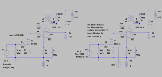
Theoretically you can make it work with your 840 but with some effort. You then have to use a negative voltage under the source-resistor to bias it.
A depletion FET is what you need t make it easier. A commonly known is DN2540 but I guess Michael has choosen the one he uses for some good reason. With the massive local feedback you get over the plastic it will surely work.
I1 resp. V4 is for adjusting bias.
Attachments
Last edited:
The good thing about the current mode driver is that it only needs to swing the pentode grid voltage. All of the feedback voltage appears between the plate and grid of the output tube (sort of...)
I guess it's not really the same as 100% voltage feedback but the result is similar in terms of output resistance and linearity. I'll post a scope shot of what the grid voltage looks like and you will be able to see why a triode is nonideal.
The reason for the 01N100 is mainly that it's my go-to depletion FET these days. One feature I like is a somewhat larger threshold voltage, which allows a glueless cascode connection as well as higher Rset values which in this case allow a >3V peak input swing with a reasonable idle current of 4 mA. A D3A would be harder to use here. As a note, high gm is not particularly useful for the input device. The high gm of this device is scaled back to about 1.5mA/V by the 820 ohm Rs. This scheme is more linear than using a low gm device I suppose. Also I think with the tube cold there could be some healthy drain-source voltage applied.
I would have gone for lower Zpri but I used the lowest Z OPT I have on hand. I think ~2K-3K would be good, and it wouldn't have to have much inductance with 200 ohms driving it. Edit: you might need to raise the g2 voltage a bit with lower Zpri in addition to lower Vp and higher idle current.
The cathode is bypassed to B+, and the screen is dropped from B+ also, for the purpose of floating any power supply ripple off the high impedance drain connection of the driver. It seems to work quite well
The bias is not particularly stable as you might imagine, with 4mA dropping across 100K, but the 1K additional DCR in the cathode helps stabilize the idle current. A more complex circuit could have gyrators, etc. and also get the MOSFET into a higher-gm regime. But I can learn more from this one yet.
I might also try cascode connecting 2 MOSFETS for the driver. That could help with the bias stability, which is really adequate as it is but could be better.
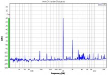
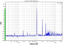
There is a bit more third harmonic than I'd like. I can't hear it but I can see it on the FFT above 1W output. I think it might be the MOSFET nonlinearity combining with the tube nonlinearity canceling some of the f2 but perhaps increasing the f3 as a side effect (another topic, another time...)
The FFT plots illustrate the f3 increasing as the output power goes above 1W. Ref 0db=1W, so the first is "small signal" of 100mW output, second is 1W out. By the time clipping starts at about 9W, the F3 and f2 are the same level. The amp sounds great so I'm not sure it's a problem, I just was a little surprised to see the f3 behavior.
I guess it's not really the same as 100% voltage feedback but the result is similar in terms of output resistance and linearity. I'll post a scope shot of what the grid voltage looks like and you will be able to see why a triode is nonideal.
The reason for the 01N100 is mainly that it's my go-to depletion FET these days. One feature I like is a somewhat larger threshold voltage, which allows a glueless cascode connection as well as higher Rset values which in this case allow a >3V peak input swing with a reasonable idle current of 4 mA. A D3A would be harder to use here. As a note, high gm is not particularly useful for the input device. The high gm of this device is scaled back to about 1.5mA/V by the 820 ohm Rs. This scheme is more linear than using a low gm device I suppose. Also I think with the tube cold there could be some healthy drain-source voltage applied.
I would have gone for lower Zpri but I used the lowest Z OPT I have on hand. I think ~2K-3K would be good, and it wouldn't have to have much inductance with 200 ohms driving it. Edit: you might need to raise the g2 voltage a bit with lower Zpri in addition to lower Vp and higher idle current.
The cathode is bypassed to B+, and the screen is dropped from B+ also, for the purpose of floating any power supply ripple off the high impedance drain connection of the driver. It seems to work quite well
The bias is not particularly stable as you might imagine, with 4mA dropping across 100K, but the 1K additional DCR in the cathode helps stabilize the idle current. A more complex circuit could have gyrators, etc. and also get the MOSFET into a higher-gm regime. But I can learn more from this one yet.
I might also try cascode connecting 2 MOSFETS for the driver. That could help with the bias stability, which is really adequate as it is but could be better.
There is a bit more third harmonic than I'd like. I can't hear it but I can see it on the FFT above 1W output. I think it might be the MOSFET nonlinearity combining with the tube nonlinearity canceling some of the f2 but perhaps increasing the f3 as a side effect (another topic, another time...)
The FFT plots illustrate the f3 increasing as the output power goes above 1W. Ref 0db=1W, so the first is "small signal" of 100mW output, second is 1W out. By the time clipping starts at about 9W, the F3 and f2 are the same level. The amp sounds great so I'm not sure it's a problem, I just was a little surprised to see the f3 behavior.
Attachments
Last edited:
#54 These are the three variants kenpeter pointed out.
R18 to the top end of R9 could have been the Mu follower I mentioned.
I wouldn't want triode plate resistance curve to become part of the divider.
15K in series helps straighten it, but doesn't swamp the effect completely.
The MOSFET's source curve is much flatter by virtue of being near zero.
Much easier to hide behind 15K and pretend to disappear from the equation.
Last edited:
As far as 100% PG feedback goes. Its a Mu=1 situation. From Plate to Cathode appears
as a Diode right on the knee. Thats why impedance is so low. But from the driving end,
a special Diode that you can modulate threshold voltage with only a fairly small current.
I was only thinkin of the concertina applications! I guess Mu=1 makes decent output
device too. The Z's are low, but we still need big output voltage swing to get any
power out. So maybe standard high Z OPT, we just take advantage the low plate Z
for damping factor? Sometimes I forget that low Z don't mean a low DC resistance...
You'd still need more than 20 of em' for OTL...
You can Schade sand down to Mu=1 fairly easy too. Unity gain splitter for sure.
Output sand sacrilege at Mu=1 is a tougher sell, but not for technical reasons.
Last edited:
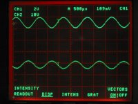
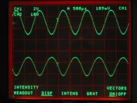
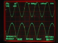
Here is what the grid waveform looks like with current mode feedback. As input signal (top trace) increases, the grid signal (bottom trace) becomes more and more "nonlinear" to compensate for output tube linearity.
Since the driver is only driving the grid voltage, what is the meaning of "mu" in the case of current mode feedback?
At full signal before clipping, the grid swings 34V P-P and the plate swings 705V P-P. Is the mu factor ~21? How is that useful against gm and effective Rp? Calculated against gm and effective Rp, mu factor is of course one or less, but the actual plate/grid signal ratio is 21. I guess a new set of parameters are needed to describe this current mode feedback circuit. It has the Zout of a cathode follower, the gain of a pentode, and the linearity of a low mu triode.
Basically, the driver is a V-to-I converter and the driver output current sets the plate-grid voltage. Thus the "feedback voltage" is developed across the resistor, from plate to grid. This results in about 1% second harmonic distortion for my load line at full signal.
Using a pentode or transistor for the driver allows the feedback to correct the grid signal as needed with the residual cathode-grid nonlinearity adding to the near-linear plate-grid swing and resulting in a percent or so f2 distortion at full signal.
If the driver were a triode with low Rp trying to maintain a sine wave output with it's own internal feedback, it would fight the feedback signal besides operating on a steep load line.
BTW
I think my third harmonic distortion reading is due to too high an input level on my A/D converter input. It goes to +18db (about 6VRMS) but starts to add distortion of it's own above about 1V input. I'll make the measurement again with a voltage scaler on the A/D input. I think the output may be distorting above 1V as well, so I'll need to check that also. I know I get my best S/N at about 1V RMS level which I am exceeding in my measurements.
Cheers,
Michael
PS the whole amp is a few components on a tube socket and a terminal strip. The MOSFET only dissipates about 1/4 W, Rfb a couple of watts, and Rk about 5 watts.
Attachments
Last edited:
So this discussion went to Schadeland. Maybe this after all is the best way to "triode-strap".
Michael,
Great work. Really like the idea. Biasing through the FET is sensitive and critical though. You don´t happen to have a DN2540 to drop in? With the 820ohm source-resistor you will need the current sink indicated in my schematic for proper biasing. Without sink I guess the source-resistor should be ca 400ohm. But as I see it, Rs is part of the local feedback against Zin of next stage. Simmed with all FET-models I have with 820ohm and this one looked best . Seems to follow your IRL measurements well.
Also tried 68k-130k FB resistors but that didn´t change much, maybe 100k was a little better. The balance between 2nd and 3rd harmonics was what changed.
.Michael,
Great work. Really like the idea. Biasing through the FET is sensitive and critical though. You don´t happen to have a DN2540 to drop in? With the 820ohm source-resistor you will need the current sink indicated in my schematic for proper biasing. Without sink I guess the source-resistor should be ca 400ohm. But as I see it, Rs is part of the local feedback against Zin of next stage. Simmed with all FET-models I have with 820ohm and this one looked best . Seems to follow your IRL measurements well.
Also tried 68k-130k FB resistors but that didn´t change much, maybe 100k was a little better. The balance between 2nd and 3rd harmonics was what changed.
- Status
- This old topic is closed. If you want to reopen this topic, contact a moderator using the "Report Post" button.
- Home
- Amplifiers
- Tubes / Valves
- Most linear triode-strapped pentode