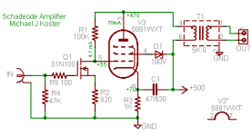
The good thing about the current mode driver is that it only needs to swing the pentode grid voltage. All of the feedback voltage appears between the plate and grid of the output tube (sort of...)
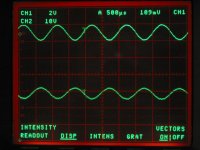
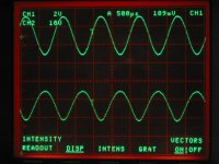
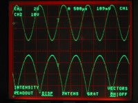
I guess it's not really the same as 100% voltage feedback but the result is similar in terms of output resistance and linearity. I'll post a scope shot of what the grid voltage looks like and you will be able to see why a triode is nonideal.
The reason for the 01N100 is mainly that it's my go-to depletion FET these days. One feature I like is a somewhat larger threshold voltage, which allows a glueless cascode connection as well as higher Rset values which in this case allow a >3V peak input swing with a reasonable idle current of 4 mA. A D3A would be harder to use here. As a note, high gm is not particularly useful for the input device. The high gm of this device is scaled back to about 1.5mA/V by the 820 ohm Rs. This scheme is more linear than using a low gm device I suppose. Also I think with the tube cold there could be some healthy drain-source voltage applied.
I would have gone for lower Zpri but I used the lowest Z OPT I have on hand. I think ~2K-3K would be good, and it wouldn't have to have much inductance with 200 ohms driving it. Edit: you might need to raise the g2 voltage a bit with lower Zpri in addition to lower Vp and higher idle current.
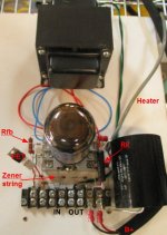
The cathode is bypassed to B+, and the screen is dropped from B+ also, for the purpose of floating any power supply ripple off the high impedance drain connection of the driver. It seems to work quite well

The bias is not particularly stable as you might imagine, with 4mA dropping across 100K, but the 1K additional DCR in the cathode helps stabilize the idle current. A more complex circuit could have gyrators, etc. and also get the MOSFET into a higher-gm regime. But I can learn more from this one yet.
I might also try cascode connecting 2 MOSFETS for the driver. That could help with the bias stability, which is really adequate as it is but could be better.
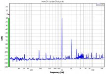
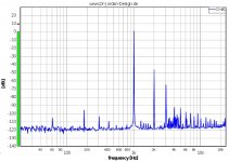
There is a bit more third harmonic than I'd like. I can't hear it but I can see it on the FFT above 1W output. I think it might be the MOSFET nonlinearity combining with the tube nonlinearity canceling some of the f2 but perhaps increasing the f3 as a side effect (another topic, another time...)
The FFT plots illustrate the f3 increasing as the output power goes above 1W. Ref 0db=1W, so the first is "small signal" of 100mW output, second is 1W out. By the time clipping starts at about 9W, the F3 and f2 are the same level. The amp sounds great so I'm not sure it's a problem, I just was a little surprised to see the f3 behavior.
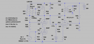
 and wonder if it would work with a IRF840 (I have a number of these) and at a lower voltage (B+ 370V) while dropping the OPT impedance to 3.5k. (or even 2.5k)
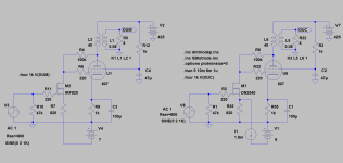