There is no AC signal on the drain of the MOSFET (the drain is grounded AC wise through the PSU) so there can be no feedback that way (nothing to feed back, just a static DC bias conditiion).
The last paragraph on that page speaks only about cathode degeneration as the form of feedback that lowers the distortion and it's irrelevant from the "turn penthode into triode" point of view.
I was never scared of being a fool in public , not being exception even this time ..... so I'm staying with claim that there is Shade effect here , call it feedback or not
drain is on same potential all the time , but there is pretty visible and significant modulation across 10K resistor , which is , if you ask me or not , pretty much sole condition to have what's claimed
Thermal stability should be ok due to source resistor. I have not decided yet on good start up scheme, trying to avoid relay to speaker output. Probably shorting the cathode of 6SN7 to 5.25V for 90s during startup can prevent turn on thump. No idea on turn off thump. Needs a build to be sure, currently still gathering parts.... did you get to organizing start-up arrangement and did you tested DC stability ?
.....
Hi Zen Mod.
1k and 10k is standard for any schade application with irfp240 or depends on current and gain?
...... shamefully I'm constantly lazy to search ,then to know whom I need to credit for ......
finally
it's revintage , posted (as far as I'm able to find) for first time here :
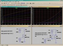
O.H. Schade (1938) meets MOSFET
 to ZM. I played a bit with #133 idea and got really good result. Negative H2 phase when gain of the N mosfet is higher than the P mosfet (R15 < R16). This idea made harmonic adjustment (similar to P3 in F5) available to M2 output stage. Comments?
Attachments

There is no AC signal on the drain of the MOSFET (the drain is grounded AC wise through the PSU) so there can be no feedback that way (nothing to feed back, just a static DC bias conditiion).
Does the transistor know this?

Does it need to "know" in order to behave in certain manner?Does the transistor know this?
It does not. The Schade connection is still there, as the same amount of
current flows through that resistor in either mode.
Of course, the effect is suppressed by all the degeneration offered by
common-drain operation.

If Schade is still in this configuration, it opens up great possibilities of application. Can we say that Schade is more of a DC bias than Feedback CA?
same as presented in original papers - it's effect is in AC domain , so feedback
for purpose of clarity , same as we can observe mosfet + source resistor as independent 3 - pin black box (having different transfer characteristic comparing to origin part) , same we can say for Schaded mosfet - new (black box ) part, with same 3 pins , having different transfer characteristic
bottle it , and call it sand triode ; we all know that triode is having intrinsic negative feedback ....... at least compared to pentode
NP made the same with LU in F3 - source resistor + LU + cascode - new 3 pin part , instead of big SIT
Last edited:
- Home
- Amplifiers
- Pass Labs
- Most Greedy Boy, of them all... or (there is no) DEFiSIT of Papa's Koans