Using multi way speaker?
No, Fostex FE168SigmaES in a QWP.
Hi Sam,
Good, easier to listen to phase changes with full range.
Since you have output capacitor, you have 2 easy change that may give different sound signature.
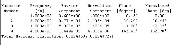
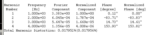
At current output point of #170 (source of M1) and your bias, my sim show negative ~170 deg H2. You may :
1. move connection point of output capacitor to source of M2 and listen. Sim show positive ~100 deg H2 if you do this. Presentation will be more forward.
2. then reverse speaker connection and listen. Sim show negative ~80 deg H2 if you do this. Presentation will move back.
Still too shouty? Do you have the R5 (10k) - C1 (680p) zobel at the input like original M2? You may want to add them if you do not and still think the presentation is too shouty.
Have fun.
Good, easier to listen to phase changes with full range.
Since you have output capacitor, you have 2 easy change that may give different sound signature.
At current output point of #170 (source of M1) and your bias, my sim show negative ~170 deg H2. You may :
1. move connection point of output capacitor to source of M2 and listen. Sim show positive ~100 deg H2 if you do this. Presentation will be more forward.
2. then reverse speaker connection and listen. Sim show negative ~80 deg H2 if you do this. Presentation will move back.
Still too shouty? Do you have the R5 (10k) - C1 (680p) zobel at the input like original M2? You may want to add them if you do not and still think the presentation is too shouty.
Have fun.
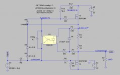

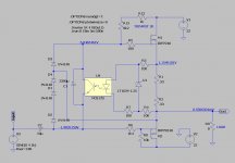
change to prescribed opto
source resistance is veeeery important
and try latest one (Schade down) with gate resistor up to 1K4
also , take care of properly taken output node
this one is on par with original M2 , at least according to sim
then , why change
disclaimer - arrangement of 3 1N4148 still needs some rethinking .......
Attachments
Last edited:

1V25 is what counts ..... type not so much
it's different in sch just because LTSpice is having this one in library , and I don't care for difference in name
as I said - you can even go without them , if you're not going beserk with input signal , when everything goes in clipping ; Papa must include them , from several reasons ;
my thinking is - if you go berserk with signal in , you deserve all possible punishments from your own DIY apparatus
(just half joking)
Last edited:
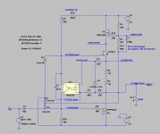
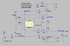
interesting thing , if you observe currents in load and outputs separately - uper mosfet is working against load and lower mosfet ....... something as lower mosfet is error correction device
that said for SEF amp , with Schade connection on lower mosfet ;
same applies for Papa's DEFiSIT ....... IRFP9240 down is doing heavy work , practically working "against" load and SIT in upper half , so SIT practically stealing some funny strange Voodoo amount of current
Papa , care to comment , anything ........?
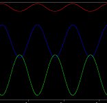
attached screenshot of currents in SEF amp , ref. to post #193 :
blue - current through load
green - current through upper mosfet
red - current though Schade connected mosfet
of course , all hell breaks loose when approaching highest amplitudes ...... I mean , I can't stop laughing , just looking at currents through mosfets and resulting current through load
Attachments
Last edited:
They don't call it degenerate for nothing.

my man .........
Attachments
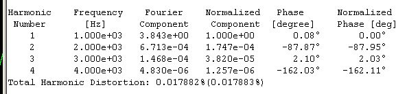
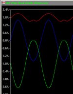
can you do the same pic for M2 config for comparison, pls?attached screenshot of currents in SEF amp , ref. to post #193 :
can you do the same pic for M2 config for comparison, pls?
nothing to write home about - each mosfet having exactly 50% of current swing , and they're summing through load ; OK - small difference , resulting from difference in their xconductance , but practically that's that
..........
of course , all hell breaks loose when approaching highest amplitudes ...... I mean , I can't stop laughing , just looking at currents through mosfets and resulting current through load
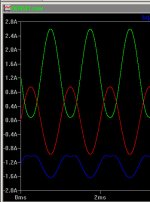
speaking of that ....... attached SEF sim screenshots ; blue current through speaker , green current through non-altered mosfet , red current through Schade-d mosfet ; 30Vpp input signal
Attachments
- Home
- Amplifiers
- Pass Labs
- Most Greedy Boy, of them all... or (there is no) DEFiSIT of Papa's Koans