didn't I pointed you before to my post in M2 thread , where I (little clumsy) explained how optocoupler thingie works ?
will this attachment help ?
anyway - back to M2 (find schematic , they are everywhere , as is deserved)
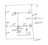
LED part of optocoupler is fed from (across) source resistors
say that current through source resistors is rising - opto LED is conducting more current , thus shining (whatever that means ) stronger
that shine is directed at paired bjt , where more shine is resulting in lower internal resistance of bjt itself ; it is connected between gates of upper and lower mosfet;
each gate is connected with , say , 47K to adjacent rail , so two 47K resistors and bjt in between are forming bridge between rails , and current through that bridge is - look back - governed by LED shine
so , back again , current through source resistors is rising , so voltage across them ; LED shines more , opening BJT
current through both 47K resistors is rising , thus voltage across them increasing ...... result is - two gates squeezing together , thus closing mosfets
so , current thrugh source resistors is decreasing , led is shining less , closing bjt .... current through 47K resistors decreasing , so is voltage across them ........ moving gates away of each other ....... opening mosfets ........ and here we go again
entire mechanismus explained here is somewhat exaggerated , things are much tinier and in equilibrium
now - Babelfish M25 is different from M2 in one tiny detail - there are no source resistors at mosfets , so their role are taken by current sensing chips in rails - current is rising , resulting voltage at IC is rising ;
voltages of two Hall chips are summed and taken to optocoupler , working pretty mach same as in M2
did I forgot something ?
oh yes ....... Ugs of SIT and mosfet , for same current , is not the same ; to put sources on proper voltage level , one just need to elevate/move gates somewhere from zero potential and that's easy - making those two "47K" resistors unequal
so - optothingy is taking care of (voltage ) distance between gates , while values of these two "47K" resistors are taking care where gates are gonna be , thus sources too ....... simply because sources always tend to follow gates
")
will this attachment help ?
anyway - back to M2 (find schematic , they are everywhere , as is deserved)
LED part of optocoupler is fed from (across) source resistors
say that current through source resistors is rising - opto LED is conducting more current , thus shining (whatever that means ) stronger
that shine is directed at paired bjt , where more shine is resulting in lower internal resistance of bjt itself ; it is connected between gates of upper and lower mosfet;
each gate is connected with , say , 47K to adjacent rail , so two 47K resistors and bjt in between are forming bridge between rails , and current through that bridge is - look back - governed by LED shine
so , back again , current through source resistors is rising , so voltage across them ; LED shines more , opening BJT
current through both 47K resistors is rising , thus voltage across them increasing ...... result is - two gates squeezing together , thus closing mosfets
so , current thrugh source resistors is decreasing , led is shining less , closing bjt .... current through 47K resistors decreasing , so is voltage across them ........ moving gates away of each other ....... opening mosfets ........ and here we go again
entire mechanismus explained here is somewhat exaggerated , things are much tinier and in equilibrium
now - Babelfish M25 is different from M2 in one tiny detail - there are no source resistors at mosfets , so their role are taken by current sensing chips in rails - current is rising , resulting voltage at IC is rising ;
voltages of two Hall chips are summed and taken to optocoupler , working pretty mach same as in M2
did I forgot something ?
oh yes ....... Ugs of SIT and mosfet , for same current , is not the same ; to put sources on proper voltage level , one just need to elevate/move gates somewhere from zero potential and that's easy - making those two "47K" resistors unequal
so - optothingy is taking care of (voltage ) distance between gates , while values of these two "47K" resistors are taking care where gates are gonna be , thus sources too ....... simply because sources always tend to follow gates
Attachments
Last edited:
Hi ZM can you in general terms describe the difference ( not technical -but sound ) between Babelfish M25/SissySIT.
I currently have two types of speakers at home traditional inneffective 2way (86-87db) and effective Altec A5s and Altec 604-8g. The Altecs, although they are in the 98-100db range and can be used with 6-8W SE amps, like more for movies, prog, rock and large orchestra ( 20-40 watts eg PP EL34 and F6).
) between Babelfish M25/SissySIT. I currently have two types of speakers at home traditional inneffective 2way (86-87db) and effective Altec A5s and Altec 604-8g. The Altecs, although they are in the 98-100db range and can be used with 6-8W SE amps, like more for movies, prog, rock and large orchestra ( 20-40 watts eg PP EL34 and F6).
Last edited:
I could say that these are two different tools for different tasks
one of my guys asked me the same question yesterday ; I told him : "while you're still having Dynaudio Contour 1.8 , Babelfish M25 will do the job ....... and if you pony up for those 10" Tannoys I told you about , SissySIT will be better "
I called PapaSIT amps like this :
DEFiSIT (so SIT-3) : Pleasure Device
SIT-2 :Orgasmotron
SIT-1 :Orgasmotron^2
while Babelfish M25 is simply Berserked M2
edit: these Altecs you have are simply no good ; send them to OPLDF , and care would be taken
Give me that PCB Might Man!
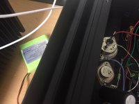
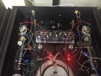
I tried THF51 into the battery biased DEFiSIT.
These wild horses insist Vgs of -0.3V and -1.1V respectively. Ha ha..
I managed to bias them and am listening to them. I had to switch the polarity of CCS circuit.
Even these horses can be used in your circuit? I hope so.
If you know of a quiet bias supply that can replace batteries, please give me tip. Of course until I can use some nice PCB of yours
I tried THF51 into the battery biased DEFiSIT.
These wild horses insist Vgs of -0.3V and -1.1V respectively. Ha ha..
I managed to bias them and am listening to them. I had to switch the polarity of CCS circuit.
Even these horses can be used in your circuit? I hope so.
If you know of a quiet bias supply that can replace batteries, please give me tip.
Of course until I can use some nice PCB of yours Attachments
Last edited:
....
These wild horses insist Vgs of -0.3V and -1.1V respectively. Ha ha.. ......
you mean - difference between gates , one channel 0V3 and other 1V1 ?
to be more specific , just measure Vgs of each of them , and write here
example - both THF51-S I used in SissySIT prototype are having -3V40 for 2A Iq , while one IRFP9240 is 4V1 , second is 4V5
that means , in first channel , there is (4V1-3V4)= 0V5 window to squeeze optocoupler bjt in , while in second channell window is (4V5-3V4)=1V1
silly me , I didn't even selected those IRFP9240 ...
Last edited:
OK , numbers don't lie ....... but how's that , just -0V33 and -1V1 , for THF ??
I didn't measured them at other voltages/currents other than those interesting to me
so these are values for 15V of Uds and Iq 1A5 ? , where (just) 15V is obviously dominant
conclusion - for any selection , same must be done on intended rail voltage and intended Iq
logical , taking in account their resistive character


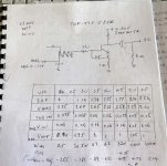
table handy to have everywhere
sorry , dunno who originally made it
edit: as I understand it , to Vbias written in table , you need to add voltage sag across 1R in source , to have effective Ugs
editedit: oh , yes , there is , in lowest row
sorry , dunno who originally made it
edit: as I understand it , to Vbias written in table , you need to add voltage sag across 1R in source , to have effective Ugs
editedit: oh , yes , there is , in lowest row
Attachments
Last edited:
Thanks for the comments. I already have an Orgasmotron in my 300b monoblocks ( WE91 variants ) so Berserk is probably more for me
Would not send my baad Altecs even to my worst enemy. Will lock them up in my cellar to keep sensitive audiophiles and innocent bystanders out of harms way
Would not send my baad Altecs even to my worst enemy. Will lock them up in my cellar to keep sensitive audiophiles and innocent bystanders out of harms way
I could say that these are two different tools for different tasks
one of my guys asked me the same question yesterday ; I told him : "while you're still having Dynaudio Contour 1.8 , Babelfish M25 will do the job ....... and if you pony up for those 10" Tannoys I told you about , SissySIT will be better "
I called PapaSIT amps like this :
DEFiSIT (so SIT-3) : Pleasure Device
SIT-2 :Orgasmotron
SIT-1 :Orgasmotron^2
while Babelfish M25 is simply Berserked M2
edit: these Altecs you have are simply no good ; send them to OPLDF , and care would be taken

- Home
- Amplifiers
- Pass Labs
- Most Greedy Boy, of them all... or (there is no) DEFiSIT of Papa's Koans