Here it is again:
http://www.diyaudio.com/forums/attachment.php?attachmentid=200182&stc=1&d=1291907862
http://www.diyaudio.com/forums/attachment.php?attachmentid=200182&stc=1&d=1291907862
Attachments

http://www.diyaudio.com/forums/attachment.php?attachmentid=200257&stc=1&d=1291953183
Here is another way to match two FETs. We are measuring the current (two current-meters connected to FET sources) flowing through both FETs at the same Vgs. You do not need absolutely identical current-meters becasue at 1-1.5A the difference 0.01V at gates will give us 50mA difference in currents via FETs (for IRFP240s). As well this schematic allows to mount FETs at the same heat sink w/o insulating thermal pads.
If you do not have two current-meters or you want to be absolutely precise measuring the current, you can use one DPDT switch to connect current-meter to first or second FET source (the switch should connect a FET source to the ground directly or via current-meter).
Attachments
Last edited:
Mosfets testing
Creaked
I had been trying to test mosfets and to achieve repeatable results and almost given up
While trying to match the mosfets the rise in temperature kept giving me a rising Vgs
As Papa said you need to do the matching all on the same day as environmental conditions change.
Read his paper
But what if we find a way to get around this.
All I want is to select a few that appears to be ok if I get rid of 50% of the bad ones when on the actual build it can be improved upon to achieve perfection (no wander I newer finish anything she says still got a quarter of a tile to fit under the cooker from 3 years ago)
Many tanks to Frags whom protested a couple of brilliant diagrams
Those are on my tread mosfets testing. The rest is just clasick LM317 stuff just let me know if you get stuck but nothing new there.
Once the temperature is constant this settles but is very difficult to keep the temperature constant so what if we compare 2 mosfets subjected to the same environmental conditions.
See picture 1
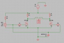
The following is a Vgs match test for FQP19N20 P to test FQA12P20 just invert polarities of the power supply
Values of the resistors can change as long as those are matched between the left and right branches (but maybe no need to)
2 mosfets are thermally coupled to a convenient heat sink one of the Left is the “compensating device” the one of the right is the mosfets under test.
The mosfets due to be tested are kept in contact with the heath sink and are therefore kept reasonably close to the same temperature.
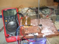
Picture 10 shows the actual circuit.
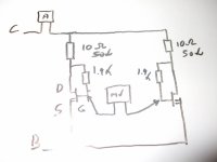
A supply voltage (+ in case of N channels) Egg 10 V is fed to the Drain by a 10 ohms 25W resistor the voltage to the gate is fed from the drain of the mosfets to the gate with a 1K resistor (in my case 1k9)
The sources are connected to the PSU return.
Matching those is quite important as it gives more manageable results are not really necessary but it helps.
At times normal DM is not accurate enough for measuring resistive values with precision there is always ohms law to help
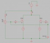
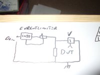
Picture 6 is a diagram for a variable current source using a LM 317
By adjusting the trim pot a constant current is fed to the Resistor under test
I have set this at 100 mA for the 10 ohms power resistors.
By applying ohms law measuring the voltage drop at this constant current gives an accurate resistive values.
Of 4 samples I had readings of 1.0621 1.0547 1.0429 1.0648 V corresponding to 10.06 10.05 10.04 10.06 ohms
For the circuit I have selected the 2 10.06 ohms resistors.
The same can be done for the 2 1K resistors connected to the gates
As I had a few 1K92 RC55Y I did not bother.
Test procedure
Important factor is the thermal coupling gets this right and it becomes easy
The left is the compensating device it will stay there at all times
On the right the DUT (device under test)
Current is set at any value you may like as long as the heath sink cope with it
To test at operating values is best.
Lets start with 1A each more or less
The meter set in the mV range measure the voltage difference at the connation between Left resistor and drain and the right resistor and drain
I had a few rounds of test for now keep changing mosfets on the right the time to perform the test was the time taken for the reading to settle 1 to 2 minutes
But I had a play with a 10-minute test and it did not change things at all
Test 1 19 mV
Test 2 8 mV
Test 3 11mV
Test 4 23 mV
Test 5 10mV
Note test 3 and test 5 only 1 mV difference between the 2 this is what I am looking up for on the test 3 and 5 are pretty close got my first matched set
Test 4 and test 2 quite a large difference there so they will be used for something else
If I did not match the resistors the difference between compensating and DUT would have been larger this would not make any difference as matched mosfets are the one that give you the same reading say a 56mV would match with a 57mV
Craked?
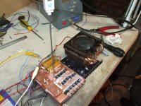
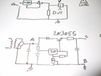
PS Just to complicate maters I had a quick stab at pulling 2 A on each branch sink went up to 50C and then I kept it there for a good 5 minutes I am using a old CPU fan to keep the sink at a reasonable temperature again a LM317 and the power supply is one more LM317 and 2N3055 just to have a variable voltage at 5or 6 A
Picture list
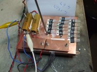
Picture1 and 3
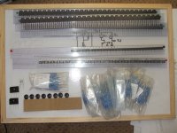
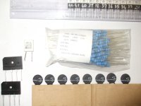
The rig note power resistors and mosfets clamps thermal coupling + mosfets ready to be tested kept at similar temperature.
If you like to cheat just tighten or loosen one of the bolts perfect results alla time
Picture 6 constant current from LM317
Picture 7 you know what this is
Picture 8 PSU SET UP clasick LM317
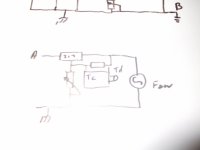
Picture 9 fan speed control (need same work but it works handy if you stick one inside the amps
Picture 10 the test diagram
Tanks again Frags
I kept the best for last
The Frags Bridge
Creaked
I had been trying to test mosfets and to achieve repeatable results and almost given up
While trying to match the mosfets the rise in temperature kept giving me a rising Vgs
As Papa said you need to do the matching all on the same day as environmental conditions change.
Read his paper
But what if we find a way to get around this.
All I want is to select a few that appears to be ok if I get rid of 50% of the bad ones when on the actual build it can be improved upon to achieve perfection (no wander I newer finish anything she says still got a quarter of a tile to fit under the cooker from 3 years ago)
Many tanks to Frags whom protested a couple of brilliant diagrams
Those are on my tread mosfets testing. The rest is just clasick LM317 stuff just let me know if you get stuck but nothing new there.
Once the temperature is constant this settles but is very difficult to keep the temperature constant so what if we compare 2 mosfets subjected to the same environmental conditions.
See picture 1
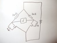
The following is a Vgs match test for FQP19N20 P to test FQA12P20 just invert polarities of the power supply
Values of the resistors can change as long as those are matched between the left and right branches (but maybe no need to)
2 mosfets are thermally coupled to a convenient heat sink one of the Left is the “compensating device” the one of the right is the mosfets under test.
The mosfets due to be tested are kept in contact with the heath sink and are therefore kept reasonably close to the same temperature.
Picture 10 shows the actual circuit.
A supply voltage (+ in case of N channels) Egg 10 V is fed to the Drain by a 10 ohms 25W resistor the voltage to the gate is fed from the drain of the mosfets to the gate with a 1K resistor (in my case 1k9)
The sources are connected to the PSU return.
Matching those is quite important as it gives more manageable results are not really necessary but it helps.
At times normal DM is not accurate enough for measuring resistive values with precision there is always ohms law to help
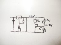
Picture 6 is a diagram for a variable current source using a LM 317
By adjusting the trim pot a constant current is fed to the Resistor under test
I have set this at 100 mA for the 10 ohms power resistors.
By applying ohms law measuring the voltage drop at this constant current gives an accurate resistive values.
Of 4 samples I had readings of 1.0621 1.0547 1.0429 1.0648 V corresponding to 10.06 10.05 10.04 10.06 ohms
For the circuit I have selected the 2 10.06 ohms resistors.
The same can be done for the 2 1K resistors connected to the gates
As I had a few 1K92 RC55Y I did not bother.
Test procedure
Important factor is the thermal coupling gets this right and it becomes easy
The left is the compensating device it will stay there at all times
On the right the DUT (device under test)
Current is set at any value you may like as long as the heath sink cope with it
To test at operating values is best.
Lets start with 1A each more or less
The meter set in the mV range measure the voltage difference at the connation between Left resistor and drain and the right resistor and drain
I had a few rounds of test for now keep changing mosfets on the right the time to perform the test was the time taken for the reading to settle 1 to 2 minutes
But I had a play with a 10-minute test and it did not change things at all
Test 1 19 mV
Test 2 8 mV
Test 3 11mV
Test 4 23 mV
Test 5 10mV
Note test 3 and test 5 only 1 mV difference between the 2 this is what I am looking up for on the test 3 and 5 are pretty close got my first matched set
Test 4 and test 2 quite a large difference there so they will be used for something else
If I did not match the resistors the difference between compensating and DUT would have been larger this would not make any difference as matched mosfets are the one that give you the same reading say a 56mV would match with a 57mV
Craked?
PS Just to complicate maters I had a quick stab at pulling 2 A on each branch sink went up to 50C and then I kept it there for a good 5 minutes I am using a old CPU fan to keep the sink at a reasonable temperature again a LM317 and the power supply is one more LM317 and 2N3055 just to have a variable voltage at 5or 6 A
Picture list
Picture1 and 3
The rig note power resistors and mosfets clamps thermal coupling + mosfets ready to be tested kept at similar temperature.
If you like to cheat just tighten or loosen one of the bolts perfect results alla time
Picture 6 constant current from LM317
Picture 7 you know what this is
Picture 8 PSU SET UP clasick LM317
Picture 9 fan speed control (need same work but it works handy if you stick one inside the amps
Picture 10 the test diagram
Tanks again Frags
I kept the best for last
The Frags Bridge
Attachments
-
 Mosfet testing 001.jpg589.8 KB · Views: 275
 -
 Mosfet testing 003.jpg599.6 KB · Views: 264
 -
 Mosfet testing 006.jpg542.3 KB · Views: 266
 -
 Mosfet testing 007.jpg527.8 KB · Views: 237
 -
 Mosfet testing 008.jpg565.8 KB · Views: 232
 -
 Mosfet testing 009.jpg294.1 KB · Views: 93
 -
 Mosfet testing 010.jpg460.2 KB · Views: 81
 -
 The FRAGS bridge.jpg611.9 KB · Views: 94
comparison matching
Nice test rig.
Good procedure to remove the effect of unknowns from the testing.
The only difference in my preferred method is that rather than having two separate gate supplies, I use one adjustable resistor ladder from +v to -v and tap off the divided voltage to feed both gates with a 100r in each feed.
Then one only has to monitor the Id measuring bridge to see good or very good matching.
Initially I test for Id at bias current and group the FETs by this parameter.
Then pick two that gave close test Id and move to variable Id matching.
The gate voltage adjustment allows Id to be swung over a range of currents to see how well or how badly the pair track each other.
 It's a pity that I had to delete a post with 95% technical content. bksabath is officially warned that a repetition will cause immediate Sin Bin.
I have managed to get consistent VGS readings on different days by keeping the test rig temperature constant.
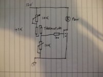
Cheap and nasty but with parts I have for the F5
May be good for fan variable speed control
PT1 set the temperature the other pot the rate of change of the voltage applied to the gate
Values that work for me are 100K PT1 and 17 K for the other TH is the stock thermistors
Ps I have quite a few spares
So if interested let me know
Holco 15ppm 2W 10 47 100 150 R looking for £0.2
And FQP19N20p (TO220) at about £5
Soon Futaba 0.47R and FQA12P20
Attachments
- Status
- This old topic is closed. If you want to reopen this topic, contact a moderator using the "Report Post" button.
- Home
- Amplifiers
- Pass Labs
- Mosfet testing