Same progress
I have made same more progress on Mosfet testing
See the attached documents
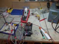
The spreadsheet shows a preliminary test on one of the Mosfet from cold
And I mean 7.2C cold at start up.
At the moment is all on a breadboard and should be beter once properly built
still from spread sheet 2 it shows a 15 minute test and the values cycle up and down in less than 15 minutes and are whith in the 2nd decimal place
I will ran the same test tomorow if I can and I expect I should get similar results
Tanks to Nelson Pass for the Matching Mosfet article from which this is derived
Al
I have made same more progress on Mosfet testing
See the attached documents
The spreadsheet shows a preliminary test on one of the Mosfet from cold
And I mean 7.2C cold at start up.
At the moment is all on a breadboard and should be beter once properly built
still from spread sheet 2 it shows a 15 minute test and the values cycle up and down in less than 15 minutes and are whith in the 2nd decimal place
I will ran the same test tomorow if I can and I expect I should get similar results
Tanks to Nelson Pass for the Matching Mosfet article from which this is derived
Al
Attachments
suddenly - mosfet matching is rocket science .
This comment bothers me! this is just the wrong attitude!
I have read, re-read and re-re-read both of Nelsons articles as well as Rod Elliot's article on mosfet testing and their are quite a few questions that are left unanswered! and now that I have built my own mosfet tester based on both articles and a HV power supply i have even more questions! So i really feel the subject is worth discussing.
I work on big high watt professional power amplifiers and i need to be able to match mosfets so these big amps will STAY running while getting the crap beat out of them night after night! and so there are a whole bunch of variables that might affect what decisions are made to match devices for those amps vs say a home amp.
after experimenting and testing several batches of IRFP240/9240 Mosfets at both 10V and 100V the numbers end up all over the place. How i would have matched these devices at 10V is not how I would have chosen to match them at 100V, or at 20, 40, 80v or whatever.
Now i understand what we are looking at is the curve of the device and a curve tracer really is the way to match devices. but at the moment that is not an option.
So I keep going back to...what is the MOST important parameter and is that different for different situations? would a class A amp want devices matched differently than say a class AB amp? or how about for a pro PA amp? or how about for rail switches in a class H amp? How about matching for a class D amp where the device is full on/off? all of these things "May" need a different parameter for best matching? I don't know the answer to that. but there is a bunch of questions right there and each of those probably has 3-4 or more questions based on the answers given and so on and so forth, rinse and repeat!
Do we want devices that are matched when idle? IE match at the bias current? or would it make more sense to do something like calculate what 1/3 power would be (worst case dissipation scenario) and match at that level? But that may mean that while they are all pulling there weight evenly at the worst thermal condition, there is more distortion at idle? etc etc etc.
So yes, this really is a complicated subject and I am looking for answers!
I have talked to many manufacturers and the answers have been all over the place. one company matches at 15V and says that is all they ever needed to do. but those amps are rarely driven hard. another mfg says they don't match at all - which explains why i fix LOTS of there amps! another company matched for thermal characteristics but that company is now gone and there is no information on how it was done. another matches for distortion and i am sure if i keep asking i will get even more answers...
So its not such a cut n dried subject.
Last edited:
.......
Now i understand what we are looking at is the curve of the device and a curve tracer really is the way to match devices. but at the moment that is not an option. ........
my comment was exactly having on mind that conclusion you also wrote itself ;
if you aren't in situation to do exactly this , there is no much you really can do - except to match them exactly in working condition - meaning on Iq and Uq , in same time
Greedy Boyz routinely match them just for Iq ,considering that in Papa amps outputs are working in class A (they're pretty awake in these conditions ) but there is certainly another set of problems when you're using mosfets in B class amps ......
anyway - you can make differential tester - with one mosfet as "etalon" one and another as DUT, but you need controlled temperature for both etalon and DUT ; you can look for steady state condition symmetry , or you can chase lowest asymmetry in amplification mode
choose your own poison ...... or choose one of giants and ask him for opinion and never look back
it seems that one of them make multi-output devices amps , and I know at least for few of these amps even working in extremely heavy conditions

it was fun seeing Stasis amp - driving 4 La Scala's in discotheque
 (chest pressurizing )
some Peavey half ton bastard was driving 4 KH's ( tummy pressurizing )
Hi Zero Cool
It did bother me as well
You have 2 choices speak up your mind and end up in the Sinn bin or ignore.
If you geet binned they win.
(Still wort it at times)
There is a dude that can only be compared to a mispelled RX8 engine but if you give what you get your post diappear just like that.
Don't get me wrong I am getting to like Zen in a funny sort of way and getting used to the lack of imputs and the patronising remarks so I don't bother to get upset any more.
Is just Zen having his little stab well if he pleases him.
There are quite a bit of other members here that are much worst and at the same time same really amazing and dedicated peoples.
Umans in the universal sense
Tanks for posting
As you say it is a pain to match and All I am trying to do is to get the best few out of a bunch If I cut the number in half once on the field it will take me less time to select the good ones
I have chosen parameters not to far away to the real ones so it should not be too bad
And I am doing this the DIY way if you need to match for work it might be useful to get a proper temperature controller set up temperature is the real pain IMO
Just by walking past that rig on the scurfy bench they get upset.
There is no difference on where you use the bugghers. I use to have to carry the lot on board of petrol rigs as I was using them as Ultrasound PWM 36KHz 1600V 16KW Systems a real pain can't they make them to blow open circuit?
Al
Mosfet test update
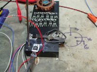
Much warmer in the loft today 7.7 C
Also still on the bread board and the supply to the gate is not regulated so that may be what moved the goal post
But even on those condition the 2nd Decimal place is on target
Time to put the lot on a PCB and make things a bit better
The temporary Rig (heat sink and such) works a treat it may be to large causing a bit of lag on the control of the temperature
Slices of foam between same of the fins should take care of that
N° CH1(Vdc)
1 3.4337 31 3.435 61 3.4357
2 3.434 32 3.4351 62 3.4357
3 3.434 33 3.4353 63 3.4356
4 3.4341 34 3.4354 64 3.4355
5 3.4336 35 3.4355 65 3.4352
6 3.4336 36 3.4356 66 3.4352
7 3.4333 37 3.4356 67 3.4351
8 3.4333 38 3.4353 68 3.435
9 3.4329 39 3.4352 69 3.4349
10 3.4329 40 3.4353 70 3.435
11 3.4328 41 3.4354 71 3.4348
12 3.4329 42 3.4355 72 3.4348
13 3.4328 43 3.4357 73 3.4347
14 3.4328 44 3.4358 74 3.4347
15 3.433 45 3.4357 75 3.4346
16 3.433 46 3.4359 76 3.4345
17 3.4331 47 3.4358 77 3.4345
18 3.4331 48 3.4358 78 3.4343
19 3.4331 49 3.4358 79 3.434
20 3.4331 50 3.4359 80 3.4338
21 3.4331 51 3.436 81 3.4337
22 3.4332 52 3.4361 82 3.4336
23 3.4332 53 3.4361 83 3.4337
24 3.4332 54 3.4361 84 3.4336
25 3.4333 55 3.436 85 3.4337
26 3.4333 56 3.4358 86 3.4336
27 3.4333 57 3.4358 87 3.4336
28 3.4334 58 3.4358 88 3.4336
29 3.4333 59 3.4357 89 3.4333
30 3.4346 60 3.4358 90 3.4333
91 3.4333
at 42 fan on 120seconds for temperature to start to drop
Test at 10 S interval
I'll draw a schematic tonight and upload it with more details.Please tel me more
Al
- you can make differential tester - with one mosfet as "etalon" one and another as DUT, but you need controlled temperature for both etalon and DUT
There's another way of matching FETs if you have two matched resistors (0.1% or better).
In this case voltage regulation and FET temperatures are not a problem at all.
Using this method you will match two FETs connected at the same time with same conditions.
differential test, compare DUT to REF.this sound very good
Please tel me more
Exactly, and, if you place both of them at the same heat sink with the same thermal pads close enough, the temperature drift will now be an issue.differential test, compare DUT to REF.
You have to do a lot of testing to assure perfect matching, and
this is not usually practical. That's why there are ballast
resistors on the Source pins - to improve the equality of
behavior.
For Mosfets I simply test Vgs under typical idle conditions
and use parts from the same lot code. In actual output
stages with lots of parallel devices this works fine.

this is not usually practical. That's why there are ballast
resistors on the Source pins - to improve the equality of
behavior.
For Mosfets I simply test Vgs under typical idle conditions
and use parts from the same lot code. In actual output
stages with lots of parallel devices this works fine.
Nelson, you are 100% right.
When I bought 20 IRFP240s from mouser I got maximum Vgs difference 6mV at 1-1.5A Iq.
It means that the transistors manufactured under same conditions (some equipment, timestamp, etc) are very very close to each other and do not require an extra effort to match them.
When I bought 20 IRFP240s from mouser I got maximum Vgs difference 6mV at 1-1.5A Iq.
It means that the transistors manufactured under same conditions (some equipment, timestamp, etc) are very very close to each other and do not require an extra effort to match them.
Last edited:
You have to do a lot of testing to assure perfect matching, and
this is not usually practical. That's why there are ballast
resistors on the Source pins - to improve the equality of
behavior.
For Mosfets I simply test Vgs under typical idle conditions
and use parts from the same lot code. In actual output
stages with lots of parallel devices this works fine.
For a conventional amp i agree but what about matching for rail switches where there are no source/drain resistors?
For this it does not matter at all. Not big deal if one FET has ON resistance 18mOhm and another 19mOhm.For a conventional amp i agree but what about matching for rail switches where there are no source/drain resistors?
Bksabath,
Here is the schematic for differential FET testing

You need to measure the voltage difference between FET drains which should be zero in case of two absolutely equal FETs.
With the potentiometer you can set desire current via FETs.
R5 and D1 for FET gate protection and can be omitted.
Temperature drift will equally affect both FETs if are they mounted at the same heat sink.
Again, you need to match R1 and R2 as close as you can.
Here is the schematic for differential FET testing
You need to measure the voltage difference between FET drains which should be zero in case of two absolutely equal FETs.
With the potentiometer you can set desire current via FETs.
R5 and D1 for FET gate protection and can be omitted.
Temperature drift will equally affect both FETs if are they mounted at the same heat sink.
Again, you need to match R1 and R2 as close as you can.
Last edited:
- Status
- This old topic is closed. If you want to reopen this topic, contact a moderator using the "Report Post" button.
- Home
- Amplifiers
- Pass Labs
- Mosfet testing