Don S said:
ZenMod, thanks for the info. I went with the 610's so that I could keep it simple. Maybe next update will include the jfets and cascode. ............
Thanks, DonS
but- that's just two more eeny weeny BC critters and two resistors
")
Unless you know of a jfet with 200 volt rating!
now ya teasing me..........
same to you !!!!

Don S said:
What I am asking is, we should be looking for equal voltage across drain to source of both Q6 and Q4, correct?
Or maybe better said is drain to + rail for Q6 and drain to - rail for Q4 should be equal and opposite, correct?
DonS
Is there math that will help calculate this (R1)? Am I on the right path?
Don S said:
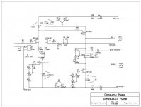
Please see my attached full schematic. No fets for drivers or outputs. Just good old bjt's!
My other concerns are my fb arrangement, taken from the drivers, not the outputs. Like Threshold. Also the A40 bias tracking from the output emitter resistor.
Have a look and let me know what you think!
Can anyone comment on this arrangement?
DonS
Don S said:
Is there math that will help calculate this (R1)? Am I on the right path?
DonS
ZM:
to answer on Q - for Q6 and Q4 Ugs-es will be same only if they are strictly matched.........and there is no need for that, and that isn't your goal at all
calculate R1 for 4V across it; simple .
DonS:
Can anyone comment on this arrangement?
I told you- to me knowledge, that's good for start .
if that arrangement was functional in Treshold and A40.......
Zen Mod said:
ZM:
calculate R1 for 4V across it; simple .
I told you- to me knowledge, that's good for start .
if that arrangement was functional in Treshold and A40.......
ZenMod, I am just looking for more viewpoints! You seem to have a lot of contacts on this forum, please have them look at this thread and comment also.
BTW just because Nelson Pass did it for a specific circuit doesn't mean it will work in mine! Mixing a bad white wine with a bad red wine doesn't make a great zinfandel.
Thanks, DonS
Don-
Try using a pot for R1 -- that would be the easiest method to get what you are looking for ( that is how I do it, if I undestand correctly, you want something like the magical 390 ohm resistor found in many of the alephs.)
otherwise, ZM gives good advice.
I am curious, is this schematic from a Threshold amp or from the A-40 or did you put it together?
Is there signal at the drain of Q4--thereby creating a true PP output?
JJ
Is there math that will help calculate this (R1)? Am I on the right path?
Try using a pot for R1 -- that would be the easiest method to get what you are looking for ( that is how I do it, if I undestand correctly, you want something like the magical 390 ohm resistor found in many of the alephs.)
otherwise, ZM gives good advice.
I am curious, is this schematic from a Threshold amp or from the A-40 or did you put it together?
Is there signal at the drain of Q4--thereby creating a true PP output?
JJ
jupiterjune said:Don-
Try using a pot for R1 -- that would be the easiest method to get what you are looking for ( that is how I do it, if I undestand correctly, you want something like the magical 390 ohm resistor found in many of the alephs.)
otherwise, ZM gives good advice.
I am curious, is this schematic from a Threshold amp or from the A-40 or did you put it together?
Is there signal at the drain of Q4--thereby creating a true PP output?
JJ
jj, I plan on trimming R1 for best balance. I am just curious to see what the math might be.
I put it together this circuit. It does use the bias feedback of the A40, and the feedback path of the later stasis models that say overall fb free.
Q4 is just a current source/sink. Q6 is the se output of the vas stage. It's drain has the positive drive output on it. Q5 is the Vbe multiplier. for the purpose of the signal just think of it as a resistor. It drops a few volts by the time we get to the drain of Q4. Therefore giving you your negative drive.
In order to have a complimentary pp vas Q4 would be driven from the drain of Q2 through a level shifter. (Accually I think that statement it wrong!)
In order to have a comp pp vas you would need to have a p channel long tail pair and drive Q4 from that.
Someone want to help me here!
DonS
Don S said:Mr. Pass, please help! After all you got me into this hobby with the A40!
As far as I can see, the original schematic with the voltages
you provided should work fine, you just need some heat sinking
on the output devices.
Q1 will not turn on. Q2 is very hot! It's over 55C. Q3 is over 45C (it has a heatsink, stamped metal) and continues to climb along with the current through R5.
From ground there is no voltage to Q1 gate, Q2 gate has over 9 volts.
Only R1 has changed from the schematic to 1k0.
I am lost! Please help!
DonS
From ground there is no voltage to Q1 gate, Q2 gate has over 9 volts.
Only R1 has changed from the schematic to 1k0.
I am lost! Please help!
DonS

more mosfet problems...
AF-2 120W-250W MOSFET Power Mono Amplifier ( 6 lbs.) 89.80 114.80
I bought a MOSFET at markvelectronics.com, but the advertised part is still posted for $89.80. Are they out of business??? ( http://www.markvelectronics.com/store/ )
My warranty will up be soon-but I'm still covered, but THEY DON'T ANSWER THE PHONE!
Anyone help?
Thanks, Miron Cheld
Can someone look at the voltages and let me know what is going on. Is Q6 shorted or is the gate overdriven, or is it something else I am missing.
Q4 is heatsinked and gets to hot to touch afteronly a minute or so. My calculation for Q4 is 58v + 75v - 1.9v = 131.1 X 19mA = 2.5watts. Is my math correct?
Mr. Pass? Anyone?
DonS
Q4 is heatsinked and gets to hot to touch afteronly a minute or so. My calculation for Q4 is 58v + 75v - 1.9v = 131.1 X 19mA = 2.5watts. Is my math correct?
Mr. Pass? Anyone?
DonS
Attachments
The long tail pair just quit again. Are Q2 and Q6 oscillating because I don't have any feedback as configured? Should I tie drive+ and drive- together and tie them to the feedback? At least for testing the front end?
Also after rereading the A75 article (thanks JJ) I believe that I don't have enough fb. If the article is correct here are my calculations.
r12+r13/r12=85.8 for the gain factor. If I change r12 to 1k5 I am now at about 32 for the gain factor, correct? And if so do I need to change R8 to 1k5.
Help!
DonS
Yes I have a cooler head today!
- Status
- This old topic is closed. If you want to reopen this topic, contact a moderator using the "Report Post" button.
- Home
- Amplifiers
- Pass Labs
- Mosfet Frontend Troubles