Don S said:I have tied drive+ and drive- to the fb. I also changed R12 to 1k5. I also replaced Q6 at the same time.
I still have ~60+ volts at the tie. Shouldn't Q2 be trying to correct for this offset? Should I raise R2 for more gain stablity in Q6?
What am I missing?
DonS
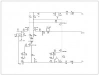
I have attached the updated schematic to help with this!
DonS
Attachments
The long tail pair just quit again
Try putting zener protection diodes on the gates, at least for troubleshooting. When I was trying to figure out a problem with my Mini aleph, I went for about 3 weeks without blowing the input mosfets. Then I took out the protection zeners -- I blew 3 or 4 input mosfets in 2 days--mostly due to startup transients, I think.
Hmm--by the voltages you posted, it looks like the DC voltage back to the gate of Q2 would be very high, enough to smoke Q2. I am somewhat of a noob, though....Is Q6 shorted or is the gate overdriven, or is it something else I am missing
I can't quite get exactly what is happening there.
JJ
It appears that R2 should be at ~68R. If Q4 and Q6 are close to complimentary, then don't we want to keep the gate to source voltages similar? If Q4 and Q6 both approximate two resistors for the sake of DC in this circuit, if we equal resistance ( of Q4 and Q6 we will see 0v between them )! Referenced to ground that is.
Have I had too many beers?
Comments?
DonS
Have I had too many beers?
Comments?
DonS
JJ, if the feedback network is looked at as a simple resistor divider network then 60+ volts should be looked at as R13+R12/R12=32.6! 60+volts/32.6=1.84volts at the base of Q2. (This is also what I measured!) Correct me if I am wrong.
And I probably am wrong! LOL! It's true!
DonS
And I probably am wrong! LOL! It's true!
DonS
JJ, if the feedback network is looked at as a simple resistor divider network then 60+ volts should be looked at as R13+R12/R12=32.6! 60+volts/32.6=1.84volts at the base of Q2. (This is also what I measured!) Correct me if I am wrong.
OK--I didn't really notice the value of R12=560 (hopefully I am reading that right).
Like I said, I don't really have the expeience compared to a lot of the other guys here, so if it looks like that I can't help, I will probably just watch this thread and hopefully learn.
I did spend a good couple of months playing around with my aleph-m, trying to improve the sound. There is a cap n the negative input network, so no DC from the feedback can go to ground. In the aleph, feedback to the diff. pair is what keeps the output DC offset low, and if I understand things correctly, so should it be in your amp. When I tried to bypass this input capacitor, my output disappeared. Perhaps the same thing is happening here???
Like I said--I may be at the limits of my ability to add useful input.
JJ
edit--if I had read your post about the feedback more carefully, I would have noticed this before.....

jupiterjune said:
OK--I didn't really notice the value of R12=560 (hopefully I am reading that right).
Like I said, I don't really have the expeience compared to a lot of the other guys here, so if it looks like that I can't help, I will probably just watch this thread and hopefully learn.
I did spend a good couple of months playing around with my aleph-m, trying to improve the sound. There is a cap n the negative input network, so no DC from the feedback can go to ground. In the aleph, feedback to the diff. pair is what keeps the output DC offset low, and if I understand things correctly, so should it be in your amp. When I tried to bypass this input capacitor, my output disappeared. Perhaps the same thing is happening here???
Like I said--I may be at the limits of my ability to add useful input.
JJ
edit--if I had read your post about the feedback more carefully, I would have noticed this before.....
JJ, can you send me a schematic of your amp? It may help me with this quest.
I have changed the value of R12 to 1k5, the gain factor would be ~85
 at 562R. I forgot to change it when I misordered parts and got 47K5's instead.
Because feedback is not 100% at DC (no cap) the calculated offset adjustment by the diff pair is only about ~3%. 3% of 60 volts is only an adjustment of 1.8 volts as I calculate this. Looking at this now I see why most designs have 100% fb at DC.
Thanks to all the people that are helping. Thanks, JJ
DonS
Don S said:It appears that R2 should be at ~68R. If Q4 and Q6 are close to complimentary, then don't we want to keep the gate to source voltages similar? If Q4 and Q6 both approximate two resistors for the sake of DC in this circuit, if we equal resistance ( of Q4 and Q6 we will see 0v between them )! Referenced to ground that is.
Have I had too many beers?
Comments?
DonS
Feel free to jump in!
I want to test my theory but I am running low on semi's.
If I increase the value of R2 to ~56R, VGS of Q2 will go down, correct? Then conduction of Q2 will go down, correct?
If I do this, gain of Q6 will go down, but it's gain will be more stable, correct. (More local fb)
Is this correct and what any additional downsides are there to changing R2 to ~56R?
?????????????
DonS
JJ, can you send me a schematic of your amp? It may help me with this quest
Don- It is just basically a mini-aleph. I did put j-fets in the front end, re-sized the front end current source to 12mA or so, and re-sized the 390 ohm resistor in the front end using a pot (which I did wrong and now I have 300mV dc offset--soon it will be back on the bench.)
Grey's Mini-A
JJ
jupiterjune said:
Don- It is just basically a mini-aleph. I did put j-fets in the front end, re-sized the front end current source to 12mA or so, and re-sized the 390 ohm resistor in the front end using a pot (which I did wrong and now I have 300mV dc offset--soon it will be back on the bench.)
Grey's Mini-A
JJ
If my thinking, and math is correct, with a 12mA current source your new R3 value should be about ~780R to 860R, correct?
Who said you can't help anymore? Oh, you did!
Thanks, JJ
DonS
If my thinking, and math is correct, with a 12mA current source your new R3 value should be about ~780R to 860R, correct?
aah....I think I see. I typically measure 13.5 volts at the drain of the diff. pair transistor -- so you looked at the resistances to calculate an expected voltage????
I checked my notes to confirm that I did set the current at 12mA, and not say...17mA or so -- and of course I am once again kicking myself for not properly recording things 'as built'. So my 12mA figure might be off...
The resistor value I came up with was 590 ohms. --But as I said, (due to a faulty meter, it seems to read AC on the DC mV setting), I have 300mV of DC offset.
I wonder if resistance within the input transistor (mosfet or j-fet) would affect the size required?
JJ
jupiterjune said:
aah....I think I see. I typically measure 13.5 volts at the drain of the diff. pair transistor -- so you looked at the resistances to calculate an expected voltage????
I looked at the currents in Grey's circuit and calculated the voltage across R3 ~4.9V.
I checked my notes to confirm that I did set the current at 12mA, and not say...17mA or so -- and of course I am once again kicking myself for not properly recording things 'as built'. So my 12mA figure might be off...
I did the math and if your diff current is 12mA then to get ~4.9V across R3 is ~816R.(4.9V/6mA=816R)
The resistor value I came up with was 590 ohms. --But as I said, (due to a faulty meter, it seems to read AC on the DC mV setting), I have 300mV of DC offset.
If 590R is close for R3, then ~4.9V/590R=8.3mA and 8.3mA X 2 = 16.6mA on the diff pair.
I wonder if resistance within the input transistor (mosfet or j-fet) would affect the size required?
The CCS will do whatever it can to maintain the current you have set no matter what device is used. That is the beauty of it as opposed to a resistor, then the device would make a difference.
I hope this helps. It helps me to cement the operations of these circuits in my head.
If I have made a mistake somewhere let me know!
DonS
Responding to your email request:
given the most recent schematic and your statement that
the output voltage is about +60V,
What is the voltage across R16?
What is the voltage across R5?
What is the voltage across R1?
What is the voltage across R2?
What is the voltage across R3?
What is the voltage across R4?
What is the voltage at the Gate of Q1?
What is the voltage at the Gate of Q2?
What is the voltage across the Leds 1-3?
What is the voltage across the Leds 4-6?
Nelson Pass said:Responding to your email request:
given the most recent schematic and your statement that
the output voltage is about +60V,
What is the voltage across R16? (1.9V)
What is the voltage across R5? (2.0v)
What is the voltage across R1? (6.27)
What is the voltage across R2? (1.4V across 56R now!)
What is the voltage across R3? (.62V)
What is the voltage across R4? (.33V)
What is the voltage at the Gate of Q1? (0V)
What is the voltage at the Gate of Q2? (1.8V)
What is the voltage across the Leds 1-3? (5.2V)
What is the voltage across the Leds 4-6? (5.2v)
There you go! I think changing R2 to 56R would help. (My belief is that the VGS of Q6 was too high!) Now I think it is because the diff pair are not matched and adjusting P1 doesn't balance the currents through R3 and R4. Correct?
Is there an easy way to calculate VGS for Q6 to balance it's conductance with Q4 for 0DC offset? Or is my logic flawed?
Thank you for you help!!!!!!!!!!!!!
DonS
whoa! this one was biggie!!

Nelson Pass said:Responding to your email request:
given the most recent schematic and your statement that
the output voltage is about +60V,
What is the voltage across R16?
What is the voltage across R5?
What is the voltage across R1?
What is the voltage across R2?
What is the voltage across R3?
What is the voltage across R4?
What is the voltage at the Gate of Q1?
What is the voltage at the Gate of Q2?
What is the voltage across the Leds 1-3?
What is the voltage across the Leds 4-6?
Vix said:Now, who will answer all those Nelson's questions??
I did in my reply. We have to see what Mr. Pass' answer will be! Those are actual voltage readings. Look 2 posts up!
Doctor what is the problem?
Just waiting for the docs reply.
DonS

OK, so Q4 is conducting 19 mA, and Q6 is conducting 25 mA,
and we have a clear explanation as to why you have a positive
output.
Manwhile, your front end is not doing much to correct this, since
it is not responding to a 1.8V differential.
I would start by replacing R3, R4, and Q1 and Q2. Q1 and Q2
should be matched. I would temporarily remove R38 and P1,
connecting the Drain of Q3 to the center point of R3 and R4,
and see what happens.
- Status
- This old topic is closed. If you want to reopen this topic, contact a moderator using the "Report Post" button.
- Home
- Amplifiers
- Pass Labs
- Mosfet Frontend Troubles