Nelson Pass said:Perseverance is everything.

Mr. Pass, I have a couple of questions that I hope you might answer. I have tried to research them, however the topics quickly get over my head at this point. The answers will give me something to learn/ponder while I wait for more mica caps.
1. The lag compensations caps (miller caps I believe) are doing what to the circuit? What is the downside of using them, and is there a practical value limit? Why is the circuit reacting the way it is? (The frontend seemed stable with FB until the FB came from the EF stage.)
2. What criteria should I be using for assessing circuit stability? (I only have a 20meg scope (analog), signal generator, and 50W 8R inductive resistor.)
3. Without a complete redesign of my circuit, what suggestions can you give me to improve its audio (not instrument) performance? (Different bias levels, current mirror on the diff pair, different devices, etc.)
Thanks, DonS
Just trying to Persevere!!!!!!!!
Nelson Pass said:Let's just hack through this before getting fancy.
You'll be able to see the oscillation with a 20 Meg scope, and
you'll be able to start worrying about the other issues after
you take care of this one.
Mr. Pass, I am with you on the above statement. I would just like to know what the lag compensation is doing, and why I need it? Just a thumbnail answer will do.
Thanks, Don
Nelson Pass said:Let's just hack through this before getting fancy.
You'll be able to see the oscillation with a 20 Meg scope, and
you'll be able to start worrying about the other issues after
you take care of this one.
Mr. Pass, my other important question is, how do I define stability? When I can raise the input level and frequency as high as I want, without bias through the output emitter resistors increasing?
Thanks, DonS
Nelson Pass said:The lag compensation is going to slow down the stage until
its unity gain value is below the oscillation frequency.
Mr. Pass, is this open or closed loop gain of the (VAS?) you are talking about?
Would adding some capacitance from the drain of Q6 to the node of R11, R13 and R12 help also?
Thanks, DonS
Don S said:Would adding some capacitance from the drain of Q6 to the node of R11, R13 and R12 help also?
Feel free to try something and see what happens.
Updates and Issues
I have a (working) amp now!
No oscillations that I can detect. With or without a load it appears stable at any reasonable bias. (I tested up to ~161mA (~38mV) through one of the emitter resistors)
No input signal seems to cause trouble either. (Square, Sine, Triange at up to ~2Mhz) Although at those frequencies what goes in does not come out looking much like the input.
I ended up with Vgs comp caps of 82pF across both Q6 and Q4 to get this performance. I also upped C1 from 47pF to 470pF. I did this to help keep nasties out. It may be too high a value as I didn't take into account the capacitance of Q1's gate to ground effect in this circuit. Input from anyone?
Issue 1
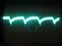
So now that this engine is running I need to get it idling smoothly. What I mean by this is that there is audiable hum/buzzing from the speaker. The oscilloscope shows several mV's of ripple at 120hz, with really quick spikes at 120hz and 240hz. (See scope shot below.)
I think that increasing R39 and R40 to 22R0 should improve this signifigantly without losing much voltage swing from the fe. (gaining ~15dB minimum of noise reduction with this change)
The other solution would be to increase the PSRR of the circuit. I just don't know how to do this easily!
Mr. Pass, and or other forum members, suggestions?
Thanks, DonS
I have a (working) amp now!
No oscillations that I can detect. With or without a load it appears stable at any reasonable bias. (I tested up to ~161mA (~38mV) through one of the emitter resistors)
No input signal seems to cause trouble either. (Square, Sine, Triange at up to ~2Mhz) Although at those frequencies what goes in does not come out looking much like the input.
I ended up with Vgs comp caps of 82pF across both Q6 and Q4 to get this performance. I also upped C1 from 47pF to 470pF. I did this to help keep nasties out. It may be too high a value as I didn't take into account the capacitance of Q1's gate to ground effect in this circuit. Input from anyone?
Issue 1
So now that this engine is running I need to get it idling smoothly. What I mean by this is that there is audiable hum/buzzing from the speaker. The oscilloscope shows several mV's of ripple at 120hz, with really quick spikes at 120hz and 240hz. (See scope shot below.)
I think that increasing R39 and R40 to 22R0 should improve this signifigantly without losing much voltage swing from the fe. (gaining ~15dB minimum of noise reduction with this change)
The other solution would be to increase the PSRR of the circuit. I just don't know how to do this easily!
Mr. Pass, and or other forum members, suggestions?
Thanks, DonS
Attachments
Ok! So while I am listing issues lets get on to the next issue.
Issue 2
When I first turn the amp on the DC offset is ~ -750mV
After approximately 10 minutes this settles to about +-50mV. It will stay stable after warmup within this range as long as I have tested. (~3Hrs)
How can I minimize the initial offset to a much lower value?
I have also noticed that at low input levels the signal shows a DC shift of ~ -0.5V. It decreases as the input signal is raised until at some point it disappears completely. (You can see it on the scope and DVM) Maybe this is another clue as to the issue?
Mr. Pass, and or other forum members?
Thanks, DonS
So on to the last issue at this point. This is for after I fix the first 2 issues. Although is might be the easiest to fix.
Issue 3
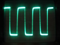
I am disappointed by the 10Khz square wave performance. (See the scope shot below.)
It shows no signs of ringing or overshoot, but the initial rise time looks a little slow and the rise time gets really slow as it approaches the peaks of the signal. (Good complimentary response though I think!) My instincts tell me this is an artifact of low negative feedback. (Possibly relatively large amounts of 2nd harmonic distortion?) (The transfer function appears to simple.) Please correct me if I am wrong. The circuit tests to ~ -2.5dB @ 100Khz with a sine wave, so I don't think circuit speed is a problem.
Mr. Pass, and or forum members please let me know what you think!
Issue 3
I am disappointed by the 10Khz square wave performance. (See the scope shot below.)
It shows no signs of ringing or overshoot, but the initial rise time looks a little slow and the rise time gets really slow as it approaches the peaks of the signal. (Good complimentary response though I think!) My instincts tell me this is an artifact of low negative feedback. (Possibly relatively large amounts of 2nd harmonic distortion?) (The transfer function appears to simple.) Please correct me if I am wrong. The circuit tests to ~ -2.5dB @ 100Khz with a sine wave, so I don't think circuit speed is a problem.
Mr. Pass, and or forum members please let me know what you think!
Attachments
Nice work!
It would be good to know what scale your scope was set at for the square wave, and also what the load was. The picture was a bit blurry -- was there some detail on the downgoing portion of the square wave that was lost by the photograph?
Unfortunately, I really don't have the technical expertise to give detailed comments on your three issues.
At this point, I would have hooked it up to some speakers already and listened to some music......
JJ
Don S said:I am disappointed by the 10Khz square wave performance.
I've seen worse.
Nelson Pass said:
I've seen worse.
LOL ROTF
How about the other 2 issues Mr. Pass!
Thanks, DonS
Nelson Pass said:Issue 2, you can capacitively couple the feedback loop or
provide some sort of "servo" mechanism for the offset.
Mr. Pass, I was thinking that maybe I could adjust the value of R2 and or R1 slightly and get some improvement. The diff pair are matched/balanced, but I am still using P1 to adjust the offset.
Why at low signal levels is the output offset drifting negative?
What value of C? should I use if I capacitively couple the FB network for maximum bass performance?
Thanks, DonS
Nelson Pass said:Issue 3
Regulate or filter the supply.
BTW this is Issue 1
Presently I am filtering the supply to the FE with a C/R/C network of 10000uF/5.6ohm/470uF.
Will increasing the R value to 22ohm help significantly? Can I easily increase the PSRR of the FE?
Thanks, DonS
- Status
- This old topic is closed. If you want to reopen this topic, contact a moderator using the "Report Post" button.
- Home
- Amplifiers
- Pass Labs
- Mosfet Frontend Troubles