No I haven't - this is why I am asking those who know.Have either of you read ESP's bit about the Disconnecting Network?
1) Earthing (Grounding) Your Hi-Fi - Tricks and Techniques
2) Here are your comments - in response to the ESP article
ESP's schematic is very misleading.
It does indeed show the Disconnecting Network attached to the Protective Earth, if one reads the diagram that way.
It should very clearly show the Protective Earth connected to chassis.
It also shows the Disconnecting Network connected to the same point on the chassis as the protective Earth. This is not necessary and is a bad practice.
The chassis must be connected permanently to the protective earth. Even when one starts opening up the case, the Protective Earth must still be connected to all conductive parts of the chassis. Some equipment will have flexible links interconnecting all removable panels to protect against accident.
The Audio Ground does not and should not use the same mechanical fixing as the Protective earth. It can be bolted on adjacent and further away. or at the speaker outlets or at the input sockets. Whereas, the Protective Earth should be a short wire welded or bolted to the chassis adjacent to the cable entry location.
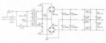
Have a look at the 4wires connected to the Rectifier. Note the labels on the 4receptacles. Is your's wired to match those labels?
_________________
regards
Andrew T.
Have either of you considered testing your proposals to see what happens when Fault Current is passed through your suggestions?
You have said
The connection between Main Audio Ground and the Chassis [must be capable of passing a 1KA of current].
and
the connection between [the Hydro] Cable PE (Power Earth ?) and Chassis must be capable of passing 1KA of Fault Current.
I'm not sure what is capable of handling a Kilo Amp.
14 awg house wiring is only rated at 15 Amps.
Please politely advise.
The only thing we want to do differently is have 2 banks of caps.
.
.
Last edited:
You have almost quoted me correctly.
I did not say 1kA, I did not specify how many kA of Fault Current could or might pass through to the PE.
kA = 1kA
The Rod Elliott article is a bit long winded - but says some good things.
1) Have a dedicated earth wire to chassis machine screw.
It can not be a dual purpose machine screw.
2) He says power toroids will induce a current in all the metal around it - including the earth wire.
So never have the earth wire form a partial turn, or more, around the toroid.
3) He says to make sure the RCA jacks are insulated from the case.
Seems painfully obvious - but was a booboo I was going to make.
4) He says its too bad that audio toroids do not have an electrostatic shield to reduce magnetic field.
I've read the electrostatic shield also reduces the coupling between the primaries and secondaries.
So this reduces hydro noise getting passed onto the secondaries.
If you saw the quality of Hydro here in Ottawa - on a scope - you'd be shocked (no pun intended).
With the Antek power toroid I have, I checked to see if the there was an outer and inner layer of windings on the primaries.
Basically the idea is that the outer part of the windings will act as a shield for the inner windings.
So the Neutral gets connected to the outer windings.
This can be checked with a scope - in the same way its done for a film cap.
Jimmy’s Junkyard Blog Archive Observing Inner and Outer Foil of Some Popular Capacitors
However, the same amount of noise was induced into the transformer regardless of which way the scope leads were connected.
.
Last edited:
I don't know. See the datasheet for thermal issues.
Right.
A good datasheet on silicon diode bridges - is not the easiest thing to find.
But here is one.
http://www.vishay.com/docs/88612/gbpc12.pdf
The answer is the temperature of the diode bridge, is not only dependent on the power it dissipates,
but also the heat sink its thermally connected to.
Regardless - the heat from a power diode bridge - near the plastic of a power transformer,
is something to be aware of.
The large rubber washer - the toroid is sitting on - should thermally protect the toroid from any heat from the diode bridge and metal case.
Here is some discussion on the issue
http://www.diyaudio.com/forums/pass-labs/121228-f5-power-amplifier-1030.html
.
Vostro,
Have you completed your power supply ?
Reading more on the subject, here are a few more things I've learned.
1) I've read that the windings on the primaries are not evenly spaced all the way around the toroid.
Nelson Pass mentions this, even with the high quality Plitron transformers he uses.
Very surprised by this.
Its kinda of basic rule to keep the windings evenly spaced all around a toroid core to keep the flux even.
The bottom line is that if you have issues with hum, rotating the toroid may help.
2) Make sure you use bleeder resistors.
Guys had have arguements where to connect bleeder resistors.
But the consensus is at the amplifier side of the bank of electrolytic caps.
3) In the Rod Elliiott article it says, when wiring the secondaries to the diode bridges,
connect exactly as shown to ensure the ripple is in phase with each amp.
Here is the first tech article I read on audio power supply design.
Solid State Power Amplifier Supply Part 1
The Guy comes across like he knows everything.
But doesn't even mention star grounding or inrush current.
... an look where he put the fuses on the secondary windings
Its no wonder you and I have made mistakes.
.
Attachments
Last edited:
As for size of those fuses I propose slow blow to value VA/V.
i.e. 500VA / (35+35) = 7.1A (7A)
As stated before my opinion was they add extra protection against shorted diode or
any short before the rail fuses come into play.
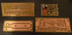
Ive been busy, turning my kitchen into a mess,
After bowls of ferric chloride and big mess with sawing and drilling, and 7hrs later,
Im finally done etching and drilling the two supply boards, protection board, and two amplifier modules.
Ive decided to build up one channel of the "blameless" type amp Ive been working on for awhile, and another module from ApexAudio SR-200,
This wold be nice to compare my new module compared to my older design.
Then also have the stunning module from ApexAudio to listen to.
Regards
Don't have all coponents yet")
i.e. 500VA / (35+35) = 7.1A (7A)
As stated before my opinion was they add extra protection against shorted diode or
any short before the rail fuses come into play.
Ive been busy, turning my kitchen into a mess,
After bowls of ferric chloride and big mess with sawing and drilling, and 7hrs later,
Im finally done etching and drilling the two supply boards, protection board, and two amplifier modules.
Ive decided to build up one channel of the "blameless" type amp Ive been working on for awhile, and another module from ApexAudio SR-200,
This wold be nice to compare my new module compared to my older design.
Then also have the stunning module from ApexAudio to listen to.
Regards
Don't have all coponents yet
Attachments
Last edited:
This the first serious audio power supply, I've ever built.
The point being, I read this article thinking this person was pointing out all the key items.
Solid State Power Amplifier Supply Part 1
Turns out he has missed many things to consider.
As for fuses - Looking at the Little Fuse datasheet - shows the graphs for a "fast" acting fuse start at 10ms.
I can get a cup of coffee faster than that.
.
Vostro,
Your boards look great ! Very impressive !
I'm sure you know this but
- try not to touch the exposed copper
- try to get good component lead to board copper contact, before adding the solder.
In other words, try not to bridge a connection with solder.
I've tried a few different solder alloys - but with my cheapo 25 watt iron
Cardas quad (4 metals in the alloy) seems to be the best without getting into
special temperature irons.
What are you going to use for a solder mask ?
That's the green stuff they spray on a board to stop the copper from oxidizing.
Do you have a spray in mind ?
When are you going into business ?
.
.
Hope you doing well with your class A,
My next major project will be a class A, about 30-50W, Im hoping.
As for the pcb, I use a product called Plastik 70, its not the greatest,
but allows me to solder through it.
I spray my boards straight after etching, so I can handle them with out oxidation.
Regards
My next major project will be a class A, about 30-50W, Im hoping.
As for the pcb, I use a product called Plastik 70, its not the greatest,
but allows me to solder through it.
I spray my boards straight after etching, so I can handle them with out oxidation.
Regards
Attachments

Hope you doing well with your class A,
My next major project will be a class A, about 30-50W, Im hoping.
As for the pcb, I use a product called Plastik 70, its not the greatest,
but allows me to solder through it.
I spray my boards straight after etching, so I can handle them with out oxidation.
Regards
Vostro,
Reading up on Plastik 70 it says its a quick drying, transparent acrylic resin.
http://www.crcind.com/wwwcrc/tds/TKC3 PLASTIK70.PDF
Watch out for the VOC's on this stuff !!! (volatile organic compounds).
You just gave me an idea.
I have a can of Dupont automotive clear coat kicking around - 60% VOC's !!! - spray and run !!!
I wonder if it would be OK to use the Dupont spray on the FR-4 (circuit board).
Dupont says its a "solvent borne acrylic melamine system."
.
Again, this is my first serious audio power supply build.
The power toroid is in the front of the amp, so the hydro has to get dragged
all the way from the back to front.
If the Hot and Neutral are twisted together, how close can I get them to the power supply electrolytic caps ?
In other words, will the electrolytic caps pick up hum from the AC lines ?
IMO: the outside of the cap's foil (toilet paper) should provide a shield for the rest of the electrolytic.
So electrolytic caps shouldn't be susceptible to magnetic fields.
Theory is nice - but experience is better.
Any one with experience with this ?
BTW: to get a nice even twist on set of wires - put one end in a vise - the other in a variable speed drill.
Works great.
If you are in the Australia, wind clockwise.
.
.
When you are assembling the power amp without a chassis, you will have a string of modules stretched across your bench/floor.
Mains connection at the left, transformer next, then rectifier, then cap bank, then amp PCB, then test load/test gear.
If you have a long length of mains cable running to that first module, you can move it around and over and under each of the other modules in turn.
If the wiring twists and PCB are done correctly you will find that you cannot detect any hum at the output no matter how close that mains cable gets. The mains cable has a three wire twist. That twisting and close coupling is the low loop area that is demanded of all the flow and return pairs. Measure the output hum with a DMM. it should be <0.1mVac. the cable should not increase the hum measurement.
Similarly you can fit an extended cable set between any of the module pairs and repeat the experiment.
You can also fit a dummy twisted pair interconnect to the amplifier input. Fit a 200r dummy Rs to that interconnect. Now move that around. Again there should be no increase in that measured hum.
I have not tried to carry out any of these experiments with an FFT testing/measuring the output.
I suspect that will be a much more sensitive test and is probably likely to show which cables do increase hum and which do not.
When you know what affects the amplifier, then you can design the packaging, i.e. how it all fits inside the Chassis and where the cables are allowed to pass/run.
Has anyone tried this FFT test for hum susceptibility of amplifier cables?
This is not the way to twist wire pairs.............. to get a nice even twist on set of wires - put one end in a vise - the other in a variable speed drill.
.........
This method puts excessive strain into both the wire and the insulation.
Hand twisting allowing the individual wires to anti rotate virtually eliminates the added stress on the wires and insulation. It's that reverse rotation of the wire strands that make the winding machines that do this so complicated. Why do they build complicated winding machines? because the manufacturers have found that not doing it results in am inferior cable!
This is not the way to twist wire pairs.
This method puts excessive strain into both the wire and the insulation.
Hand twisting allowing the individual wires to anti rotate.
Good point - I'll twist by hand.
For the Van Altine FET value 550 EX amp - for AC lines, looks like about 1 twist for every 1 1/2" - certainly as tight reasonably possible with larger gauge wires.
Where as with some other amps - such as the McCormack DNA 0.5 - the AC lines are tie wrapped close together - but not twisted.
However, in most cases, the DC lines going from the power supply to the amp are very tightly twisted.
Something in the order of 3 twists across the top of a d = 40mm cap.
.
If you have a long length of mains cable running to that first module, you can move it around and over and under each of the other modules in turn.
If the wiring twists and PCB are done correctly you will find that you cannot detect any hum at the output no matter how close that mains cable gets. The mains cable has a three wire twist. That twisting and close coupling is the low loop area that is demanded of all the flow and return pairs. Measure the output hum with a DMM. it should be <0.1mVac. the cable should not increase the hum measurement.
Similarly you can fit an extended cable set between any of the module pairs and repeat the experiment.
Exactly. after writing the post, I realized, some testing is required.
With the amp not plugged in and caps discharged,
I'm going to take a length of romex (14 awg solid core copper house wire).
Twist it - and connect AC plugs on both ends - then use it as an extension cord.
Plug a 100 watt light bulb into it.
Then connect a scope probe to the amplifier end of the bank of power supply caps.
Move the twisted AC wire around and see if a voltage can be induced.
The AC earth is connected to the bottom of the case right near where
the hydro comes into the case.
So hydro going to the power transformer will be the twisted only be hot and neutral.
Also, I don't have FR-4 boards for the power supply caps.
Caps with screw terminals are often wired p to p.
So I've wired my through hole caps P tp P.
Hope this is OK.
For a first time builder - this thread has a lot of useful in it.
Stuff I wish I knew when starting out.
If its OK with Vostro, I wonder if this thread could get moved to the power supply section of this website
Last edited:
I would use the cables joining the modules together.
That way an output from one cable becomes an input to a module and eventually that comes out as a final output. That final output changes the supply conditions and that can give rise to a further change in the signal from the interfering cable you are testing.
Using a dummy load on a separate cable does not trigger the loop into a response.
With the amp not plugged in and caps discharged,
I'm going to take a length of romex (14 awg solid core copper house wire).
Twist it - and connect AC plugs on both ends - then use it as an extension cord.
Plug a 100 watt light bulb into it.
Then connect a scope probe to the amplifier end of the bank of power supply caps.
Move the twisted AC wire around and see if a voltage can be induced.
This will not work because in this case the bank of caps is floating.
All the scope probe will pick up is 60 Hz hydro hum, whether the twisted hydro line is near them or not.
A floating row of caps (not connected to anything else), could be connected to an external power supply, set at 1Vdc.
Then a scope probe could be used to test how much hum a twisted hydro pair induces into a row of caps and associated wiring.
However, I don't think moving 120 Vac wires around a row of caps, charged to 1Vdc, is very safe.
So I'm just going to wire the power supply up.
From looking at the layout of numerous power amps,
They keep the DC wires - from the supply to the amp - well away from any AC line or diode wiring.
Also, the DC wires are heavily twisted - while the AC wires twisted or bundled close together.
.
- Status
- This old topic is closed. If you want to reopen this topic, contact a moderator using the "Report Post" button.
- Home
- Amplifiers
- Solid State
- More Supply Questions