I've just looked at a number of power amps
Perreaux 2350, First Watt, YBA 3DT, SAR Labs 450, Van Alstine FET value 550, Blue Circle BC22 MKII
Every single one of these amps has the power transformer at the front of the amp,
and the electrolytics in the mid or rear section of the amp.
This would keep the electrolytic - power transistor - speaker outputs loop short.
The disadvantage is that the AC lines would run from the back of the amp to the front.
.
Last edited:
Yes, but the mains wire pairs are twisted for low loop area. The result is they probably gain more in the very short loops that have quite spread apart terminations than they lose in the long lengths of the mains wiring.
In addition, the field emitted by the transformer is relatively far away from the input end of the amplifier board/s.
In addition, the field emitted by the transformer is relatively far away from the input end of the amplifier board/s.
Yes, but the mains wire pairs are twisted for low loop area. The result is they probably gain more in the very short loops that have quite spread apart terminations than they lose in the long lengths of the mains wiring.
In addition, the field emitted by the transformer is relatively far away from the input end of the amplifier board/s.
Andrew, thanks for your help with this.
I've just totally changed my power supply around.
Now have the power transformer at the front of the amp
- this keeps the secondaries - diode bridge - first electrolytic wire loops short
- also keeps the electrolytic output - power transistors - speaker outputs loop short
Have 2 embaressing questions - but its best to ask and make sure
1) I have a single power toriod with 2 diode bridges to make +Ve, Gnd and -Ve
From the diode bridges, is it OK to connect 2 banks of electrolyitcs ?
2) There is the 10 ohm resistor that has chassis earth on one end - audio ground at the other.
Where is the best physical location to connect the audio ground side of this resistor ?
Thanks,
See discussion in this very thread! It is easy to get the grounding wrong and send charging pulses where you don't want them to be.From the diode bridges, is it OK to connect 2 banks of electrolyitcs ?
The same principles apply, but the junction of the bridge outputs replaces the transformer CT.
- make sure there are no ground loops
- twist every pair of lines there is
- keep the diode wiring short
- keep the cap - amp - speaker output lines short
- take the amp power from the opposite end of the diodes
Maybe it would be best to show a complete schematic
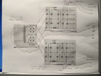
So here is the layout/schematic
Power transformer is at the front of the case
Hydro earth is connected to the case at one end of the 10 ohm resistor
The other end of the 10 ohms is connected to one ground of the electrolytics
The ground from the electrolytics goes to the amp - to create an audio star ground
Then ground goes to the speaker output.
Any corrections ?
.
Attachments
You appear to have separate grounds for the two channels, but connected in the PSU by wires carrying charging pulses - so the two 'grounds' will want to be at different potentials. Then it is likely that the two channels will have their grounds connected together somewhere, either in this amp or in the source - you get a ground loop.
It is quite difficult to sort out this ground mess, which is why you either need one PSU with one ground feeding both channels or two completely separate PSUs. Your hybrid solution (two PSUs fed from one set of secondaries) seems to be popular but messy. You need one ground in your PSU, not two separate grounds. As I said, this is the same as the earlier PSU but just with the bridge junction replacing the CT. You are making the same mistake as he did, so you need to change to the same solution as him.
It is quite difficult to sort out this ground mess, which is why you either need one PSU with one ground feeding both channels or two completely separate PSUs. Your hybrid solution (two PSUs fed from one set of secondaries) seems to be popular but messy. You need one ground in your PSU, not two separate grounds. As I said, this is the same as the earlier PSU but just with the bridge junction replacing the CT. You are making the same mistake as he did, so you need to change to the same solution as him.
This could kill you or another operator/user !!!!!!!!!!!......................There is the 10 ohm resistor that has chassis earth on one end - audio ground at the other..............
This could kill you or another operator/user !!!!!!!!!!!
It is my understanding that when hydro comes into the case,
the earth is immediately connected to the metal case.
I was going to use the floor of the case near the IEC connector.
The case earth and amplifier ground are separated by a 10 ohm resistor,
with 2 power diodes in parallel.
Is this correct ?
You appear to have separate grounds for the two channels, but connected in the PSU by wires carrying charging pulses - so the two 'grounds' will want to be at different potentials. Then it is likely that the two channels will have their grounds connected together somewhere, either in this amp or in the source - you get a ground loop.
... you either need one PSU with one ground feeding both channels or two completely separate PSUs. Your hybrid solution (two PSUs fed from one set of secondaries) seems to be popular but messy. You need one ground in your PSU, not two separate grounds. As I said, this is the same as the earlier PSU but just with the bridge junction replacing the CT. You are making the same mistake as he did, so you need to change to the same solution as him.
The power supply is getting totally rebuilt.
So only changes on paper are required right now.
The supply is for an amplifier biased at 1 amp with +/- 24 v rails.
The toroids I have are 400VA - so I'm just going with one.
When music is playing, some of the signal ends up on the supply rails.
I think this affects the channel separation of the amp.
So the options are
- with a completely single power supply have a very low supply Zout
- use an amp design that has a very good PSRR.
- use a Hybrid power supply.
I will rework the audio ground.
.
Yes. The connection between Main Audio Ground and the Chassis and the connection between Cable PE and Chassis must both be capable of passing kA of Fault Current..................The case earth and amplifier ground are separated by a 10 ohm resistor,
with 2 power diodes in parallel.
Is this correct ?
Originally Posted by Uunderhill View Post
.................The case earth and amplifier ground are separated by a 10 ohm resistor,
with 2 power diodes in parallel.
Is this correct ?
Andrew,
I don't know what the cable PE and chassis is ?
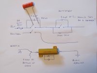
For the case earth to audio ground separation, I have the choice between
a) a 12 ohm 50 watt resistor - paralleled by a 40 Amp diode bridge
b) a CL-30 thermistor R = 2.5 R @ 25oC I(max) = 8 amps
Is the CL-30 too light for this application ?
Here is the schematic of what I have planned. Please tell me this is OK.
The contact resistance of those switches is in the order of 0.05 ohms - not thrilled about that.
.
.................The case earth and amplifier ground are separated by a 10 ohm resistor,
with 2 power diodes in parallel.
Is this correct ?
Yes. The connection between Main Audio Ground and the Chassis and the connection between Cable PE and Chassis must both be capable of passing kA of Fault Current.
Andrew,
I don't know what the cable PE and chassis is ?
For the case earth to audio ground separation, I have the choice between
a) a 12 ohm 50 watt resistor - paralleled by a 40 Amp diode bridge
b) a CL-30 thermistor R = 2.5 R @ 25oC I(max) = 8 amps
Is the CL-30 too light for this application ?
Here is the schematic of what I have planned. Please tell me this is OK.
The contact resistance of those switches is in the order of 0.05 ohms - not thrilled about that.
.
Attachments
And the connection between Cable PE and Chassis.
(Earth Wire from Mains Cable) connection to Chasis (Amplifier Enclosure)
My personal opinion is that the 12R 50W resistor (between Earth and Audio Ground) is over kill.
I use a 22R 5W resistor, and use very very high current diodes.
Regards
(Earth Wire from Mains Cable) connection to Chasis (Amplifier Enclosure)
My personal opinion is that the 12R 50W resistor (between Earth and Audio Ground) is over kill.
I use a 22R 5W resistor, and use very very high current diodes.
Regards
Last edited:
DF96,
I just want a power supply for a class A amp, biased at 1 amp.
There are 3 stages in this amp - each has a current source - so the PSRR is good.
Even so, I suspect the L and R channels would talk to each other through the supply rails.
Hence the hybrid power supply.
I've tried reading through 6L6's build of an F5 - Wish those forums would get cleaned up because amongst all the jibber, there is a lot of useful info.
Tried reading articles on audio power supplies - but they leave out key info.
Like not even mentioning softstart or star grounding.
Tried looking at professionally made amps. But its difficult to see all the details.
After reading 6L6's F5 build, I am concerned about the diode bridges getting hot
and mounting them right beside the plastic covered power toroid - yikes !
I figure if the supply rails are running at 2 Amps - each bridge will dissipate
5.2 watts = 4 diodes x 0.65v x 2 amps
Do you know if these get hot ?
.
And the connection between Cable PE and Chassis.
(Earth Wire from Mains Cable) connection to Chasis (Amplifier Enclosure)
My personal opinion is that the 12R 50W resistor (between Earth and Audio Ground) is over kill.
I use a 22R 5W resistor, and use very very high current diodes.
Regards
Vostro,
Thanks for helping out - I'm still learning here.
Hope 14 awg stranded wire is OK for the earth wire.
The biggest I can do for diodes is a 40 Amp silicon diode bridge.
I have 12 ohms at 10 watts - which could be soldered right to the diodes.
.
- Status
- This old topic is closed. If you want to reopen this topic, contact a moderator using the "Report Post" button.
- Home
- Amplifiers
- Solid State
- More Supply Questions