I had a lot of fun with this problem a few builds back. I made a masterpiece of bracketry and wire management that was a nightmare to assemble.think about maintenance when placing the different elements
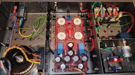
Missing from this photo is the source selector switch with its wires, coupler and shaft extension.
Removing the lid to replace tubes requires the removal of some 24 screws to get the lid off.
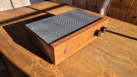
Lessons were learned......
I understand perfectly what you mean, hence my previous message.I had a lot of fun with this problem a few builds back. I made a masterpiece of bracketry and wire management that was a nightmare to assemble
I had a shoebox period, great from a research, implementation and implementation point of view but a nightmare for maintenance and according to Murphy's law, it's always where it's least accessible place where is the probleme.
G'day Guys,
I've been busy beavering away at this project.
I took me a week or two but I am (99%) done with drilling and tapping. The last couple I will sort out once I get to the wiring stage as its just P clip mounts for cable tidying.
I've had a wee holdup. My power supply with the integrated speaker protection had a rather glaring error. DC goes where the AC is supposed to go and AC goes where the DC is supposed to go.
So a fresh order from JLCpcb of updated PSU boards is on the way.
I amended my output relay board to include an output Thiel network.
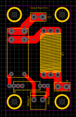
I've left enough space that I should be able to fit a pretty fat coil as require for 5uH.
I also amended my ground lift board to better fit a vertical mount 10w 10R resistor. The previous version was about 5mm short.
I had a bit of fun with broken taps in my heatsinks. Something to do with being lazy and using a drill....
One particularly nasty one required drilling a hole either side of the tap to get the broken bit out.
Exhibit A:
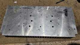
Spot the boo boo. I've fixed up the wound with some JB weld.
I will be interested to see how it goes in the long run with the different thermal expansion coefficients.
There was a few other mistakes that required the same treatment so this will be a good experiment in repairing heatsink booboos.
Luckily the most important holes that hold down the mosfets had no issues. The rest are just holding standoffs to mount the pcbs so if a failure results it won't be a huge issue to find a work around.
Once I started just tapping by hand I had no further issues. Whodathunk?
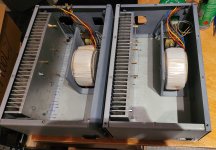
Here's a test fit of the completed board mounts.
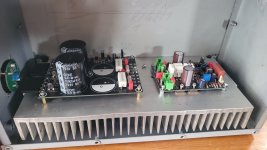
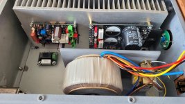
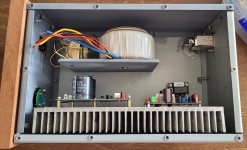
Things are pretty tight at the front of the chassis but I have some good ideas on how to work around here.
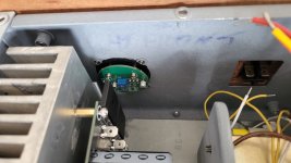
Here's a test fit of the properly tapped and mounted transformer bracket:
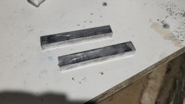
When I designed my PSU I was planning to mount the rectifiers directly to the heatsink. However I didn't account for the orientation of the rectifiers. The flat side ended up on the up side. So my solution was to buy some 10x15mm solid aluminium bar from ali express. Nobody local wanted to sell me less than 1.8m. Aliex was something like $6 including shipping for 250mm.
After cutting and a bit of linishing I got this:
Add some M3 holes for the recitifiers and some holes to go into some m4 holes in the heatsink and voila:
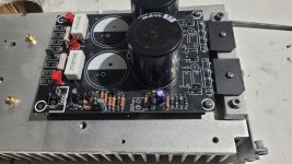
The PSU board was uncompleted for testing. It was at a stage where I could test the speaker protection circuit. However luckily I noticed the error before powering up. For now it a useful template to work around while I wait for the replacement boards.
With the heatsinks mostly dealt with. It was time for the next round of gross hole drilling. 154 holes each for the main ventilation under the heatsinks.
First to 3.5mm
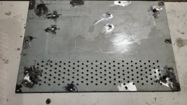
Then to 6mm with the step drill:
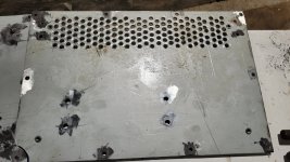
Can anybody spot the hole that somehow went wildly off centre?
I wasn't to fastidious with the hole centre accuracy on this set of holes as they are underneath. B surface and all that.
I am going to take the holes out to 7mm as I still have a bit of meat to work with.
Once I get this done I will remount the heatsinks etc and see how it looks. I think I will want to add more holes for increased airflow. However I need to figure out the placement of the output relay board before I go making holes all over the place.
That's it for now.
I've been busy beavering away at this project.
I took me a week or two but I am (99%) done with drilling and tapping. The last couple I will sort out once I get to the wiring stage as its just P clip mounts for cable tidying.
I've had a wee holdup. My power supply with the integrated speaker protection had a rather glaring error. DC goes where the AC is supposed to go and AC goes where the DC is supposed to go.
So a fresh order from JLCpcb of updated PSU boards is on the way.
I amended my output relay board to include an output Thiel network.

I've left enough space that I should be able to fit a pretty fat coil as require for 5uH.
I also amended my ground lift board to better fit a vertical mount 10w 10R resistor. The previous version was about 5mm short.
I had a bit of fun with broken taps in my heatsinks. Something to do with being lazy and using a drill....
One particularly nasty one required drilling a hole either side of the tap to get the broken bit out.
Exhibit A:

Spot the boo boo. I've fixed up the wound with some JB weld.
I will be interested to see how it goes in the long run with the different thermal expansion coefficients.
There was a few other mistakes that required the same treatment so this will be a good experiment in repairing heatsink booboos.
Luckily the most important holes that hold down the mosfets had no issues. The rest are just holding standoffs to mount the pcbs so if a failure results it won't be a huge issue to find a work around.
Once I started just tapping by hand I had no further issues. Whodathunk?
Here's a test fit of the completed board mounts.


Things are pretty tight at the front of the chassis but I have some good ideas on how to work around here.

Here's a test fit of the properly tapped and mounted transformer bracket:

When I designed my PSU I was planning to mount the rectifiers directly to the heatsink. However I didn't account for the orientation of the rectifiers. The flat side ended up on the up side. So my solution was to buy some 10x15mm solid aluminium bar from ali express. Nobody local wanted to sell me less than 1.8m. Aliex was something like $6 including shipping for 250mm.
After cutting and a bit of linishing I got this:

Add some M3 holes for the recitifiers and some holes to go into some m4 holes in the heatsink and voila:

The PSU board was uncompleted for testing. It was at a stage where I could test the speaker protection circuit. However luckily I noticed the error before powering up. For now it a useful template to work around while I wait for the replacement boards.
With the heatsinks mostly dealt with. It was time for the next round of gross hole drilling. 154 holes each for the main ventilation under the heatsinks.
First to 3.5mm

Then to 6mm with the step drill:

Can anybody spot the hole that somehow went wildly off centre?
I wasn't to fastidious with the hole centre accuracy on this set of holes as they are underneath. B surface and all that.
I am going to take the holes out to 7mm as I still have a bit of meat to work with.
Once I get this done I will remount the heatsinks etc and see how it looks. I think I will want to add more holes for increased airflow. However I need to figure out the placement of the output relay board before I go making holes all over the place.
That's it for now.
G'day Guys,
I have finished drilling the vent holes on the bottom side of the.
I think these 2 must have 20 hours of drilling and deburring between them.
First pass to 3.5mm of the 2nd set of vent holes:
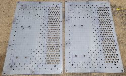
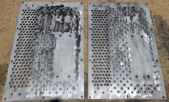
The finished set of vent holes drilled out to 7mm and deburred:
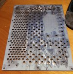
And a wee test fitting session:
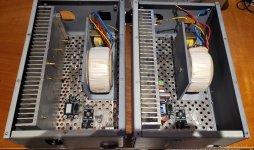
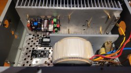
A shot from underneath:
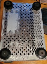
I'm very happy with how this has turned out. A lot of work but it looks cool and should provide more than enough ventilation.
I also finished the placement work for the I/O on the back panel:
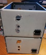
The keyways for the speaker jacks were done with a small file. A little bit rough looking but they fit snuggly.
I've gone with the Neutrik NFD style rca sockets for this build. I think they look cooler and are easier to work with the regular rca sockets.
I tried some ali express knockoffs but I wasn't happy with the quality of actual rca sockets so I replaced them with some genuine neutrik ones.
I'm debating making some more copper plaques for the power requirements and fuse spec like I did on my last tube preamp.
Next up is to place more rivet nuts in the base plates for cable tidying and then these should be ready for a coat of primer.
I have finished drilling the vent holes on the bottom side of the.
I think these 2 must have 20 hours of drilling and deburring between them.
First pass to 3.5mm of the 2nd set of vent holes:


The finished set of vent holes drilled out to 7mm and deburred:

And a wee test fitting session:


A shot from underneath:

I'm very happy with how this has turned out. A lot of work but it looks cool and should provide more than enough ventilation.
I also finished the placement work for the I/O on the back panel:

The keyways for the speaker jacks were done with a small file. A little bit rough looking but they fit snuggly.
I've gone with the Neutrik NFD style rca sockets for this build. I think they look cooler and are easier to work with the regular rca sockets.
I tried some ali express knockoffs but I wasn't happy with the quality of actual rca sockets so I replaced them with some genuine neutrik ones.
I'm debating making some more copper plaques for the power requirements and fuse spec like I did on my last tube preamp.
Next up is to place more rivet nuts in the base plates for cable tidying and then these should be ready for a coat of primer.
Well this is poos!
I was all ready to start doing some testing.
I've soldered up a test PSU to test my latest PSU design with salvaged parts before I commit good new parts.
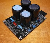
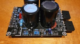
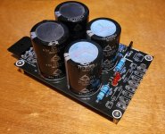
I wouldn't let these nasty Samyoung capacitors anywhere near a proper build, but their useful for testing.
This PSU has the speaker protection integarted into the PSU board to cut down on annoying wiring so I want to make sure the circuit works properly before going any further on the build.
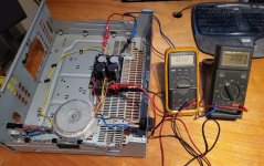
And here is the testing rig all ready to go.
And then....... Nothing.
It turns out that one of the transformers I purchased second hand some time back has a faulty primary. No continuity across the brown and blue wires.
So this puts me in a bind. I've designed this build around this pair of transformers.
I guess I am lucky I picked the faulty transformer to test with and discovered this now and not later on.
Repairing the primary is probably outside my capabilities as I doubt I could nicely rewind everything with the appropriate tension etc.
Having it repaired is, I assume even more expensive than buying a new one.
Which brings me to changing the power transformer. I do have a pair of 225VA, 2x25VAC transformers which I could use with a change to a R27 to something like 6.8k to keep the -12vdc at pin 4 of the opamp.
This might be my best option right now.
Otherwise I could have a look at my stash of salvaged power transformers.
The difficulty with my salvaged power transformer selection is that they are all EI core transformers with centre tapped secondaries. My power supply design is based on dual secondaries.
I might have some which have the secondaries that are exposed in such a way I can separate the centre tap. This might be a workable solution.
The question is whether they would fit inside the chassis, almost certainly not on the transformer bracket. However given they are home theatre amp transformers they would have an extra secondary to power the lamp on the VU meters and remove the need for the auxiliary power transformers.
I have much to think about.....
I was all ready to start doing some testing.
I've soldered up a test PSU to test my latest PSU design with salvaged parts before I commit good new parts.


I wouldn't let these nasty Samyoung capacitors anywhere near a proper build, but their useful for testing.
This PSU has the speaker protection integarted into the PSU board to cut down on annoying wiring so I want to make sure the circuit works properly before going any further on the build.

And here is the testing rig all ready to go.
And then....... Nothing.
It turns out that one of the transformers I purchased second hand some time back has a faulty primary. No continuity across the brown and blue wires.
So this puts me in a bind. I've designed this build around this pair of transformers.
I guess I am lucky I picked the faulty transformer to test with and discovered this now and not later on.
Repairing the primary is probably outside my capabilities as I doubt I could nicely rewind everything with the appropriate tension etc.
Having it repaired is, I assume even more expensive than buying a new one.
Which brings me to changing the power transformer. I do have a pair of 225VA, 2x25VAC transformers which I could use with a change to a R27 to something like 6.8k to keep the -12vdc at pin 4 of the opamp.
This might be my best option right now.
Otherwise I could have a look at my stash of salvaged power transformers.
The difficulty with my salvaged power transformer selection is that they are all EI core transformers with centre tapped secondaries. My power supply design is based on dual secondaries.
I might have some which have the secondaries that are exposed in such a way I can separate the centre tap. This might be a workable solution.
The question is whether they would fit inside the chassis, almost certainly not on the transformer bracket. However given they are home theatre amp transformers they would have an extra secondary to power the lamp on the VU meters and remove the need for the auxiliary power transformers.
I have much to think about.....
I read this as having thermal fuses on the secondaries but not on the primaries.
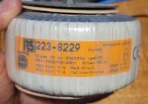
Serves me right for not checking the transformers when I received them.
I've found a pair of onkyo power transformers that would fit reasonably well into the chassis. However the unloaded secondaries are 42.6v.
Take off a couple of volts at load and we're probably looking at +/-56vdc rails which I'm guessing is a bit high?
I thought I had a pair of onkyo transformers with 36v unloaded secondaries but in my brief search last night I could only find 1 of them.
Hmmm. I would have taken that to mean you should use 5A Slow Blow fuses on the secondary.
What does the bit at the top mean? the 15/98C
(Edit... the one in the link has totally different numbers that appear to have no temperature relevance)
98C thermal fuse or just a thermal rating for the wire/transformer. I don't know.
I put the RS number into a search and got this:
https://uk.rs-online.com/web/p/toroidal-transformers/2238229
And this data sheet:
https://docs.rs-online.com/5403/0900766b815bd1de.pdf
No thermal fuse shown which means it might be worth a little pick and poke at where the wires enter just to make sure there isn't a simple fracture or something.
I was thinking along the same lines. Since it is already broken I have nothing to lose by opening it up.
I also had some time today to poke around my transformer stash. I have a pair of transformers from a Pioneer VSX515 and VSX817 which have the same Bando model number. 28VAC unloaded.
They also have the little spike type things that allow a PCB to be mounted directly to the power transformer. Which means I can theoretically separate the centre tap into dual secondaries.

This transformer is a bit large which will require some modification to the chassis but not insurmountable. 420VA according to the service manual.
I also had some time today to poke around my transformer stash. I have a pair of transformers from a Pioneer VSX515 and VSX817 which have the same Bando model number. 28VAC unloaded.
They also have the little spike type things that allow a PCB to be mounted directly to the power transformer. Which means I can theoretically separate the centre tap into dual secondaries.
This transformer is a bit large which will require some modification to the chassis but not insurmountable. 420VA according to the service manual.
Well. It pains me to admit this mistake. After destroying the power transformer I discovered It was not faulty at all.
I was simply very stupid.
The leads are magnet wire and not the normal stranded stuff one gets with more toroidal transformers.
The smart among you can see where this is going. I had simply failed to remove the enamel from the primary wires. The secondaries had obviously had this done by the previous owner of the transformers. Same with the primary on the 2nd one. This one however did not.
After working my way to the primary winding I could see no obvious damage and no thermal fuse. So I thought gee I wonder.....
Embarrassing mistake is embarrassing. Not to mention expensive: destroying a $300 transformer I can't afford to replay.
It will also cost me some time to rejig things to fit my replacement transformer options.
Sigh.
At least I now have a good stash of magnet wire.....
Absolutely. I've been caught out with not scraping wire hard enough years ago. I use a little carborundum do-dah on a PCB drill these days to clean them up. Same thing happens on super thin flexible headphone wires. They are just varnished in some way and twisted together and never seem to short internally in the lead. To thin to rub or scrape but a hot iron burns it off.
Confession is good for the soul. Also, you find out you're not alone.Well. It pains me to admit this mistake.
- Home
- Amplifiers
- Solid State
- Mooly's MMAMFM Monoblocks - A build log