G'day Guys.
I hereby start my build log for my implementation of Mooly's My Mosfet Amplifier Made For Music.
https://www.diyaudio.com/community/threads/my-mosfet-amplifier-designed-for-music.119151/
Here's the schematic for reference:

I will be implementing this amp design as monoblocks for a couple of reasons:
1) I think their cooler than stereo amps.
2) mono construction, better blah blah blah.
3) My racking situation is much better suited to my power amps being monos.
4) I like making extra power supplies etc.
I am building my chassis from scratch:
1) I have the tools, sheet metal is cheap.
2) Ali express cases tend to not be my style and shipping is horrendous to NZ.
3) I like making things for the sake of making things myself.
4) I can get exactly what I want instead of being constrained by somebody else's engineering/design choices.
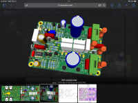
Boards have arrived fresh off of the printing press at JLCpcb.

Mmmm Shiny!
I've started populating the pcbs however today I will start the story with a peak at the current state of the chassis.

On the weekends I tend to do noisy stuff like cutting metal when I get a chance around husband/dad duties.
On weeknights I tend to work on the electronics side around exercise and husband requirements.
At my current rate of work, I would hope to have them powered up for testing in a couple of months.
I hereby start my build log for my implementation of Mooly's My Mosfet Amplifier Made For Music.
https://www.diyaudio.com/community/threads/my-mosfet-amplifier-designed-for-music.119151/
Here's the schematic for reference:
I will be implementing this amp design as monoblocks for a couple of reasons:
1) I think their cooler than stereo amps.
2) mono construction, better blah blah blah.
3) My racking situation is much better suited to my power amps being monos.
4) I like making extra power supplies etc.
I am building my chassis from scratch:
1) I have the tools, sheet metal is cheap.
2) Ali express cases tend to not be my style and shipping is horrendous to NZ.
3) I like making things for the sake of making things myself.
4) I can get exactly what I want instead of being constrained by somebody else's engineering/design choices.
Boards have arrived fresh off of the printing press at JLCpcb.
Mmmm Shiny!
I've started populating the pcbs however today I will start the story with a peak at the current state of the chassis.
On the weekends I tend to do noisy stuff like cutting metal when I get a chance around husband/dad duties.
On weeknights I tend to work on the electronics side around exercise and husband requirements.
At my current rate of work, I would hope to have them powered up for testing in a couple of months.

Of course this evening I discovered I hadn't ordered any 680R resistors for R28...
I haven't made this mistake for a while.
Otherwise I have spent the last couple of nights soldering on the resistors and zeners.

Nothing but Vishay CMF and RN for me as I like the colour and the easy to read values. I am bit colour blind so colour codes are a nightmare.
"Honey, is this red or brown?"
Costs a bit extra over say Yageo MFR series but an extra $10 over the whole build isn't much for the satisfaction of them lovely uniformly brown (red?) things.
It's mil spec so it must be better you know?
I can save money elsewhere like the $25 I saved on chassis feet by salvaging Onkyo AV receivers.
Wait till you see the salvaged heatsinks.....
I like to take my time with each part:
Takes a wee while but it hopefully cuts down mistakes and keeps everything clean and shiny
I haven't made this mistake for a while.
Otherwise I have spent the last couple of nights soldering on the resistors and zeners.
Nothing but Vishay CMF and RN for me as I like the colour and the easy to read values. I am bit colour blind so colour codes are a nightmare.
"Honey, is this red or brown?"
Costs a bit extra over say Yageo MFR series but an extra $10 over the whole build isn't much for the satisfaction of them lovely uniformly brown (red?) things.
It's mil spec so it must be better you know?
I can save money elsewhere like the $25 I saved on chassis feet by salvaging Onkyo AV receivers.
Wait till you see the salvaged heatsinks.....
I like to take my time with each part:
- make sure its the right value
- orientate the text on the resistors with the silkscreen and face the resistor value up for easy reading
- match the parts as close as possible eg: I managed to get 4 270R resistors that are exactly 270R (at least according to my old fluke)
- clean the pads with a ceramic brush before soldering
- solder each part or group of parts on both channels at a time
- solder on both sides
- clean off any solder flux residue with Iso-prop every couple of parts.
Takes a wee while but it hopefully cuts down mistakes and keeps everything clean and shiny

Time to properly introduce the chassis.
The front back and sides are 1.2mm mild steel
The top and bottom are 2mm.
I had a bit of time over the Christmas holidays to do the rather messy and noisy job of cutting the sheet metal up:

Cuts were done with one of these fancy Ryobi metal cutoff tools with the tiny 76mm 20000rpm angle grinder blades.
Their pretty good, because it has a shoe/foot I can use a straight edge as a guide and get nice straight cuts.
Folded up the front back and sides with my trusty cheap Chinese bender.


A closer look at the front/back panels


Side panels


And after much drilling and rivet nutting here's the initial assembly of the chassis:


Without the lid, we can see that there is plenty of room inside for me to take up with oversized heatsinks, power supplies etc.

The amp boards are held up at the point of soldering resistors as I need the 680R to arrive on hopefully Monday. Mouser and DHL are amazing. Typically if I order midweek: Them Texans will throw my parcel out the door to the Zee Germans who somehow get it to me by Monday. I love German logistics. I've tried Fedex and UPS and they are poos in comparison.
While I wait, I will start on the power supply boards. All going to plan I should be allowed some time away from Husband/Dad duties tomorrow to hack up some chunks of salvaged Mahogany for the front panels. Time allowing I will get some sheet metal work done too.
I attempted to jigsaw the holes in the rear panels for the IEC sockets this evening and was promptly told off by She Who Must Be Obeyed for making to much noise.....
The front back and sides are 1.2mm mild steel
The top and bottom are 2mm.
I had a bit of time over the Christmas holidays to do the rather messy and noisy job of cutting the sheet metal up:
Cuts were done with one of these fancy Ryobi metal cutoff tools with the tiny 76mm 20000rpm angle grinder blades.
Their pretty good, because it has a shoe/foot I can use a straight edge as a guide and get nice straight cuts.
Folded up the front back and sides with my trusty cheap Chinese bender.
A closer look at the front/back panels
Side panels
And after much drilling and rivet nutting here's the initial assembly of the chassis:
Without the lid, we can see that there is plenty of room inside for me to take up with oversized heatsinks, power supplies etc.
The amp boards are held up at the point of soldering resistors as I need the 680R to arrive on hopefully Monday. Mouser and DHL are amazing. Typically if I order midweek: Them Texans will throw my parcel out the door to the Zee Germans who somehow get it to me by Monday. I love German logistics. I've tried Fedex and UPS and they are poos in comparison.
While I wait, I will start on the power supply boards. All going to plan I should be allowed some time away from Husband/Dad duties tomorrow to hack up some chunks of salvaged Mahogany for the front panels. Time allowing I will get some sheet metal work done too.
I attempted to jigsaw the holes in the rear panels for the IEC sockets this evening and was promptly told off by She Who Must Be Obeyed for making to much noise.....
As I expected. I ordered from mouser at 10pm NZ time on Wednesday.
Zee Germans delivered at 11:30am on Monday.
Texas to Auckland in 5 days. NZ Post often can't get parcels from one side of Auckland to the other in that time. NZ couriers was even worse.....
There does seem to be a timing thing. It seems like DHL flies to NZ on a Friday or Saturday. If I was to order on a Monday night I typically won't see it till the following Monday.
Still. Zee Germans.....
I was testing some 2SK1058 in one of these cheap ebay component testers and I am getting some strange results.
Some look like this:

And others look like this:

The bit I am focussed on here is the capacitance measurement.
Is anybody able to shed some light on this phenomenon?
Some look like this:
And others look like this:
The bit I am focussed on here is the capacitance measurement.
Is anybody able to shed some light on this phenomenon?
Have you reversed the part in the ZIF socket? Are you getting the same result?
I've found many of those el-cheapo component testers highly suspect.
For instance on some devices one that I have here identifies small signal NPN transistors as thyristors while their PNP complementary devices look just perfect. Many of these have a calibration mode if you short all three pins and ask you for a small value film cap to verify it.
It's possible to perform other manual tests for capacitance.
Short all three pins and try again. It seems like the gate got some charging…I was testing some 2SK1058 in one of these cheap ebay component testers and I am getting some strange results.
Some look like this:
View attachment 1279303
And others look like this:
View attachment 1279304
The bit I am focussed on here is the capacitance measurement.
Is anybody able to shed some light on this phenomenon?
After shorting all 3 pins, the capacitance disappears.
If I reverse the pins around. The tester thinks it is a 500pF capacitor.
The anomaly seems to have disappeared so given the tester reads them all much the same, I will assume they are all functional.
I got about 15 of each 2sk1058 and 2sk162 on clearance from out local NZ brick and mortar electronics store Jaycar.
For $3 each, I couldn't resist clearing out the countries stock.
Given it is a legitimate retailer I will assume they are genuine. There was no proper packaging eg Antistatic etc
I think I will just grab 4 of each with the same batch code and away we go.
I think its time for some more chassis story time!
The lids are done except final paint.
There was a bit of fun involved here.
In my initial plan for the chassis I decided to go with my hole centres 5mm from the egdes.
This created some problems mainly due to not accounting for the bend radius......
So when it came to putting the rivet nuts into the front back and sides I had to move the holes a little bit away from the bend.
Which mean the holes I had already drilled on the top and bottom where not quite in the right place.....
On the bottom where nobody should be looking, I simply filed the holes into slots and called it a day.
On the top plates which I did 2nd I simply drilled another set of holes as my original holes were only 2mm as I hadn't drilled them out yet.
This allowed me to move the holes over sufficiently to make everything fit nicely but it did leave some tiny little divots around the holes which just weren't pretty enough for an A surface like the top plate.
There was also one or 2 holes where something wandered and the hole needed to be slotted a little bit.....
Exhibit A

So in a moment of genius. I wandered if I could simply bog the mistakes up. A wee google search turned up this magical stuff:
www.mitre10.co.nz/shop/j-b-weld-steel-reinforced-epoxy/p/293830
So my evil plan was to goo up my mistakes and then redrill out the holes where they should be:

After a bit of sanding flat and a bit of drilling it was like I had never made design errors or been in a rush on my metal working at all!
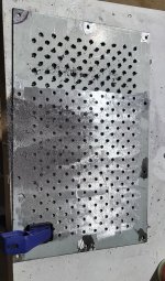
Then it was time I started on vent holes!
For the top plates I ended up with 270 holes in each one. I think it took me about an hour and a half to rule them out and centre punch them.
My poor wife had to put up with all that banging. My 2 year old girl had great fun helping daddy make all that noise. She loves playing amplifier.
I think it took me about 4 hours worth of drilling for the pair.

And then there was another couple of hours to de-burr the holes.

My trusty finger sander came to the party here to get rid of all of the 'spew' on the back side of plate from the step drill.
After all of that. A bit a lick with a 240 grit pad on the random orbit sander and a couple of coats of etch primer and voila!


The lids are done except final paint.
There was a bit of fun involved here.
In my initial plan for the chassis I decided to go with my hole centres 5mm from the egdes.
This created some problems mainly due to not accounting for the bend radius......
So when it came to putting the rivet nuts into the front back and sides I had to move the holes a little bit away from the bend.
Which mean the holes I had already drilled on the top and bottom where not quite in the right place.....
On the bottom where nobody should be looking, I simply filed the holes into slots and called it a day.
On the top plates which I did 2nd I simply drilled another set of holes as my original holes were only 2mm as I hadn't drilled them out yet.
This allowed me to move the holes over sufficiently to make everything fit nicely but it did leave some tiny little divots around the holes which just weren't pretty enough for an A surface like the top plate.
There was also one or 2 holes where something wandered and the hole needed to be slotted a little bit.....
Exhibit A
So in a moment of genius. I wandered if I could simply bog the mistakes up. A wee google search turned up this magical stuff:
www.mitre10.co.nz/shop/j-b-weld-steel-reinforced-epoxy/p/293830
So my evil plan was to goo up my mistakes and then redrill out the holes where they should be:
After a bit of sanding flat and a bit of drilling it was like I had never made design errors or been in a rush on my metal working at all!
Then it was time I started on vent holes!
For the top plates I ended up with 270 holes in each one. I think it took me about an hour and a half to rule them out and centre punch them.
My poor wife had to put up with all that banging. My 2 year old girl had great fun helping daddy make all that noise. She loves playing amplifier.
I think it took me about 4 hours worth of drilling for the pair.
And then there was another couple of hours to de-burr the holes.
My trusty finger sander came to the party here to get rid of all of the 'spew' on the back side of plate from the step drill.
After all of that. A bit a lick with a 240 grit pad on the random orbit sander and a couple of coats of etch primer and voila!
Attachments
Progress progresses.
I was allowed a little bit of cutting time amongst the weekend's chores.
-I cut out the mahogany front panels.

I was also allowed to do the steel work too!

And a test fit:

Fitting the VU meters took much longer than I would have expected.
The meters are 46mm. The closests hole saw I have is 44mm.
I used a 60grit flap wheel to take out the extra 2mm and boy does take a while on mahogany. This stuff is hard as nails.
Same on the metal. I actually did them both at the same time with the wood mounted to the steel to make sure the finished holes matched up.
Then come the harder job of dealing with the mount holes for the VU meters.
If I was smart I probably would have used some plain old wood screws....
But I am not. I wanted hex head caps screws like everywhere else on my builds.
So.... 30mm m4 bolts through the mahogany and into a rivet nut.
My drill press has a decent bit of runout so it was quite difficult to transpose the holes through the mahogany accurately onto the steel.
I managed to place the rivet nuts with decent accuracy. There was the small issue of the overhang of the flange on the rivet nuts fouling the hole for the VU meter but my trusted power file and a 60grit belt dealt with that.
Some inaccuracy remained after all was done and the meters weren't quite level. So I drilled the holes on the VU meters out an extra 1mm which gave me enough wiggle to straighten things up.

Not enough dummy bolts but you get the idea.

Back side. Also in the process, the m4 bolts to mount the wood to the steel became m6 after some alignment issues.....

And a proper test fit. Everything straight and level and purdy looking.
I will be using some nicer bolts in the end but thats a ways away at this stage.
I was allowed a little bit of cutting time amongst the weekend's chores.
-I cut out the mahogany front panels.
- Cut the holes for the power switches
- Drilled the holes for the VU meters.
- Drilled the holes for the bolts to mount to the steel inner front panel.
I was also allowed to do the steel work too!
- Jigsawed out the power switch holes
- drilled out the VU meter holes
- drilled and rivet nutted the holes to mount the mahogany
And a test fit:
Fitting the VU meters took much longer than I would have expected.
The meters are 46mm. The closests hole saw I have is 44mm.
I used a 60grit flap wheel to take out the extra 2mm and boy does take a while on mahogany. This stuff is hard as nails.
Same on the metal. I actually did them both at the same time with the wood mounted to the steel to make sure the finished holes matched up.
Then come the harder job of dealing with the mount holes for the VU meters.
If I was smart I probably would have used some plain old wood screws....
But I am not. I wanted hex head caps screws like everywhere else on my builds.
So.... 30mm m4 bolts through the mahogany and into a rivet nut.
My drill press has a decent bit of runout so it was quite difficult to transpose the holes through the mahogany accurately onto the steel.
I managed to place the rivet nuts with decent accuracy. There was the small issue of the overhang of the flange on the rivet nuts fouling the hole for the VU meter but my trusted power file and a 60grit belt dealt with that.
Some inaccuracy remained after all was done and the meters weren't quite level. So I drilled the holes on the VU meters out an extra 1mm which gave me enough wiggle to straighten things up.
Not enough dummy bolts but you get the idea.
Back side. Also in the process, the m4 bolts to mount the wood to the steel became m6 after some alignment issues.....
And a proper test fit. Everything straight and level and purdy looking.
I will be using some nicer bolts in the end but thats a ways away at this stage.
Things keep moving forward slowly but surely.
Set backs come too. I've recently broken a 2mm drill bit, an m3 tap and an m4 tap....
Taps never seem to break when you are done with them either. Its always about 3 holes from when you would be done.
Heatsink work is always fraught with such difficulties so its about time I introduced the heatsinks!
I purchased a heatsink for $50 off facebook market place.
420x40x300. It weighed 5 kilos and was clearly from something industrial. Perhaps an VFD or something similar.
I forgot to take a photo of its original form but here is the photo from the facebook listing.

So out came my trusty reciprocating saw and into 3 pieces it went.
It took me about 15minutes to make the 2 cuts. Given it was using a reciprocating saw, it wasn't quite straight. Thankfully the heatsinks will be contained inside the chassis so nobody should notice.
After the cuts I have 3 sections 140x300x40.
Miraculously, the two sections came within 2 grams of eachother at 1.6 kg each.
Overkill for some 60wattish amps. A wise old man once said (Nelson Pass I believe) that you can never have too much heatsink.
I folded up some brackets out of some salvaged 1.2mm steel. I suspect this stuff is stainless as it just has that colour too it.


This one is the "good" channel. The other heatsink had the M4 tap break on the 2nd to last hole...
I had to take some notches out of the bottom corners of the heatsinks to clear the rivet nuts that the chassis feet mount to.


Once I am done with working on them, I will tidy up the heatsinks and sand off all the scabbiness leftover from whatever it was used for before.
Next came the purchase of some 125x75x6 steel angle to make a bracket to mount the power transformers. Here is a mockup:

While I was going through the task of drilling and tapping the M3 holes to mount the amp board and power supply boards to the heatsinks.
Firstly I lost my 2mm drill bit quite early. Luckily I had a backup. Next I lost my M3 drill tap 3/4 of the way through the job.
More taps are on their way from Ali Express. After my M4 tap broke a week ago I ordered some extra M3 as well.
In the mean time I've got plenty of metal work to do around the base plate: Drilling vent holes and p clip mounts.
I'm also due to start testing the power supply with its integrated speaker protection and also the VU meter.
Plenty to keep me busy while I wait.
Set backs come too. I've recently broken a 2mm drill bit, an m3 tap and an m4 tap....
Taps never seem to break when you are done with them either. Its always about 3 holes from when you would be done.
Heatsink work is always fraught with such difficulties so its about time I introduced the heatsinks!
I purchased a heatsink for $50 off facebook market place.
420x40x300. It weighed 5 kilos and was clearly from something industrial. Perhaps an VFD or something similar.
I forgot to take a photo of its original form but here is the photo from the facebook listing.
So out came my trusty reciprocating saw and into 3 pieces it went.
It took me about 15minutes to make the 2 cuts. Given it was using a reciprocating saw, it wasn't quite straight. Thankfully the heatsinks will be contained inside the chassis so nobody should notice.
After the cuts I have 3 sections 140x300x40.
Miraculously, the two sections came within 2 grams of eachother at 1.6 kg each.
Overkill for some 60wattish amps. A wise old man once said (Nelson Pass I believe) that you can never have too much heatsink.
I folded up some brackets out of some salvaged 1.2mm steel. I suspect this stuff is stainless as it just has that colour too it.
This one is the "good" channel. The other heatsink had the M4 tap break on the 2nd to last hole...
I had to take some notches out of the bottom corners of the heatsinks to clear the rivet nuts that the chassis feet mount to.
Once I am done with working on them, I will tidy up the heatsinks and sand off all the scabbiness leftover from whatever it was used for before.
Next came the purchase of some 125x75x6 steel angle to make a bracket to mount the power transformers. Here is a mockup:
While I was going through the task of drilling and tapping the M3 holes to mount the amp board and power supply boards to the heatsinks.
Firstly I lost my 2mm drill bit quite early. Luckily I had a backup. Next I lost my M3 drill tap 3/4 of the way through the job.
More taps are on their way from Ali Express. After my M4 tap broke a week ago I ordered some extra M3 as well.
In the mean time I've got plenty of metal work to do around the base plate: Drilling vent holes and p clip mounts.
I'm also due to start testing the power supply with its integrated speaker protection and also the VU meter.
Plenty to keep me busy while I wait.
Don't forget that for your heatsinks to be effective, they need a flow of convection (I don't know the exact term in English) but they need a supply of air in the lower part, even a slight decoupling in height is enough .
That job comes very soon. I need to account for where the output relays live and some wire mounting points. Then I will start drilling a bunch of vent holes in the bottom of the chassis.
- Home
- Amplifiers
- Solid State
- Mooly's MMAMFM Monoblocks - A build log