Component values
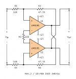
As I understand it , R3,R4 and R5 are the key components.
R5 acts as a load for the opamp and would be high , but enough to keep the device in a safe region. This current would be drawn from the power supply and through R3 and R4 for the positive and negative cycle of the signal respectively. This voltage would in turn drive the transistors.
Under zero signal conditions the transistors ( without emitter resistors) would have to be just under conduction. So 0.5 volts / quiescent current of the opamp ( monolithic amp ). With an opamp drawing say 2.8mA R3 and R4 would be about 180 ohms.
You will have to look at this closely. I am just trying to point you in the right direction.
With emitter resistors you can bias the transistors into conduction any way you want. R3 and R4 values will then be higher. But this must have some limit I guess as the supply to the opamps will also vary with the signal level !
Cheers.

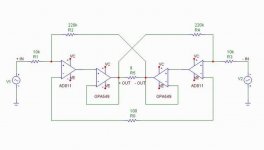
Attached below is to show the resistor values I want to have. The sizes of the resistors must affect the feedback transimpedance, frequency response and bandwidth. As expected, however, I could not figure them out. Therefore, any oipnions from all of you would much appreciate. Thanks.
JH
JH
Attachments
Re: super stuff
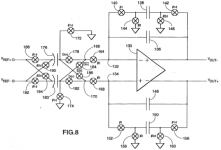
Certainly the Max435/6 was done long ago, and if you
look inside you see the parts of a differential pair driving
current sources.
All the X amps use a differential pair in concept, and making
a SuperSymmetric circuit out of this would be very easy, just
as with the "current feedback" op amps, since you have
access to a low impedance input terminal, in this case the
"Z" inputs.
What you don't see in this circuit or in the app notes is
the feedback technique as described by SuperSymmetry.
If it exists in the literature, somebody will undoubtedly
provide us with the example, but I haven't seen it yet.
(except the Hadley, which was discrete)

pass/ - will have to go on living either way.
janneman said:I think it has already been done long ago, check out the MAX435/436.
Certainly the Max435/6 was done long ago, and if you
look inside you see the parts of a differential pair driving
current sources.
All the X amps use a differential pair in concept, and making
a SuperSymmetric circuit out of this would be very easy, just
as with the "current feedback" op amps, since you have
access to a low impedance input terminal, in this case the
"Z" inputs.
What you don't see in this circuit or in the app notes is
the feedback technique as described by SuperSymmetry.
If it exists in the literature, somebody will undoubtedly
provide us with the example, but I haven't seen it yet.
(except the Hadley, which was discrete)
pass/ - will have to go on living either way.
Re: Wireless World ckt
As a variation, you could run the lower end of R5 to the two output collectors instead. Assuming the opamp output transistors are complementary-symmettry emitter followers, this would turn the outputs into Sziklai pairs. That might be interesting to play with.ashok said:Many years ago I saw the circuit attached below in Wireless World magazine. It was a suggestion to increase the output capability of an opamp.
Responding to Circlotron (love that name),
This renders the circuit unusable for X, but works fine
otherwise. Usually we see R5 going to ground and another
resistor going from the output of the op amp to the Collectors,
forming a low impedance voltage divider and giving the circuit
more voltage swing, and usually, more stability.
pass/ - all for stability, except when not.
The sw-C filter circuit below is nearly the circuit used in the output stage of AKM and Crystal/Cirrus’ 120 dB DACs – I should hope any competent patent attorney would argue sw-C circuits are equivalent “feedback means” to the resistors you use
In the Crystal/Cirrus CS43122 the differential op amp is very much the same as the OPA660/2662 tranconductance amplifier except for CMOS implementation – a complementary pair of cascoded differential pairs feed the gates of 4 common drain output fets hanging from the power supply rails (H-bridge style), local Miller caps with series Rs compensate each output fet (presumably the zero from the R is required due to the “nested” feedback C structure: “A 120dB Multi-bit SC Audio DAC with 2nd Order Noise Shaping” ISSCC 2000 paper WA20.6 (Crystal/Cirrus) and “A Multibit Delta-Sigma Audio DAC with 120-dB Dynamic Range” IEEE JSSC, v35,#8 ’00, p1066
I would be happy to receive a finder’s fee of 10% of any royalties you can collect from these big boys
Attachments
Well, you certainly get the prize for the most arcane
example I've every seen, much less imagined.
Alas, the chance that either you or I will collect royalty
money is exceedingly small.
On the other hand, I am still interested in any examples,
but let's limit it to ones before 1993.
example I've every seen, much less imagined.
Alas, the chance that either you or I will collect royalty
money is exceedingly small.
On the other hand, I am still interested in any examples,
but let's limit it to ones before 1993.
...i take it that was around the date of the first time
you got ripped off...
I know it gets said a lot, but i'm glad you decided to keep
giving to the DIY community. I'm sure you're building up
lots of extra Karma points in the process! : )
moe29 <------------ needs all the extra Karma he can get
you got ripped off...
I know it gets said a lot, but i'm glad you decided to keep
giving to the DIY community. I'm sure you're building up
lots of extra Karma points in the process! : )
moe29 <------------ needs all the extra Karma he can get
Nelson Pass said:
Best guess offhand? 100 ohms.
Better way? Find the highest value that still causes
oscillation and multiply by 5 to 10.
According to you, R0 sets the open loop gain and stability of the system. And, it would mean that the open loop frequency response is characterized here too. Therefore, the high values of feedback resistors, e.g. R2 and R4 up to about 200k, would work without any particular problem both for the system and with respect to the frequency bandwidth. Could I go ahead? I am searching shops to get the girly-man chips for another round of DIY exploring.
JH
:Off-topic:
I have only one measurement tool, Fluke Digital Multimeter. In addition to this, if I want to buy another one that is most useful for me, a hobbyist, what could you recommend? Which makes offer good price and quality? Thanks.
- Status
- This old topic is closed. If you want to reopen this topic, contact a moderator using the "Report Post" button.
- Home
- Amplifiers
- Pass Labs
- Monolithic SuperSymmetry with Current Feedback