@timgrindell mentioned the Mod-86 is the last true DIY product in the Neurochrome catalog. The LM3886DR is still there too. As far as I know though, no other truly DIY power amp product comes close to the performance of the Mod-86. An amplifier that a determined beginner with a good feel for things could probably build. This is an achievement in its own right, and adds to the cool factor of the Mod-86 a lot. I think the 100% through-hole design is the only good option for this product, to keep it accessible. The fact that you aren't using an SMD design manufactured in a machine to get these performance levels is very cool too.I see at least a couple different ways of dealing with this:
- Make a life-time buy of LM317L and LM337L from TI and keep selling Modulus-86 Stereo Kits until they run out.
- Redesign the regulator portion of the MOD86 to either use a different regulator IC or zener regulator.
- Let the Modulus-86 fade out with the LM317L and LM337L.
Buying a lifetime supply and changing the Mod-86 design are not mutually exclusive. With the lifetime supply I wonder about other parts though, they could go out under less favorable circumstances while you get stuck with the lifetime supply of parts that fit the current design. I guess this could even happen with the LM3886 itself.
Of course I have no view on the whole scale and economics of the decision. From your comments I get that there would be a minimum amount of sales (yearly for example) to make it viable to keep the product alive. I bet there's some value that's difficult to determine too, where a good experience with the cheaper Mod-86 generates interest in other products. Actually you could probably determine this by running a query on the shop database.
Regarding the voltage regulators: are there no alternative components that are compatible with pinout, specs and performance? The input buffer for Hypex and Purifi supports that typical type of voltage regulator that you see all over the DIY place. Hypex makes them, so does NewClassD, and probably a bunch of other manufacturers. I know that's all lower voltage stuff, but it makes me wonder if there's nothing else that fits the current Mod-86 design.
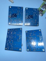
All of these are ready to go, except for the boards that don't have their IC's yet. Those will come when I get the heat sinks. Minus some parts these are the ingredients for 2x Modulus-86. I bought a revision 2.4 back in 2021, then life put some hobby-blocking events on my path. In the meantime, revision 3 was released with improved specs. The only sensible thing to do is build two amplifiers instead of one.
The PSU's are Connex SMPS300REh. The red one I bought in 2021, it's ±30 V, to be used with the revision 2.4 boards. The new one arrived with a black color (the Connex site still shows the red board), I like it. The black one is ±36 V, to be used with the revision 3 boards. Please note that Tom doesn't recommend running these boards at ±36 V. Mine will be used strictly with 8 ohm loads and I will print a warning about this on the back of the chassis.
The PSU's by Micro Audio, that Tom posted a photo of, are also looking really good. I might swap the Connex PSU's eventually (or choose the more sensible thing again: build more amplifiers).
For the revision 3 boards I have one Intelligent Soft Start and two Guardian-86's, so a complete set of Neurochrome protection and control. I still need to buy another set for the revision 2.4 build. After import tax and shipping a set of protection and control is almost 500 euro to get it to the Netherlands, or roughly one third of the total cost to build these amplifiers if you get a nice chassis machined. The protection and control are quite a chunk of the total budget, so it's tempting to skip. I want to do it right however and build them as good as I can. There's a chance these amplifiers will get used by someone else some day and I sleep better if all precautions are included.
I built a pilot project to test the Modushop production process and learn QCAD. There were some mistakes, but all in all I have a decent ICEpower 200AS2 amp working great. With the lessons learned, I ordered a 2U Dissipante for the Modulus-86 revision 3 build. If all goes well, I can build my first Modulus in January.
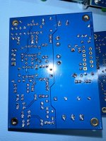
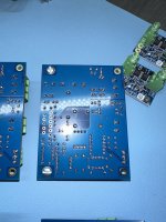
I cleaned the flux on the Modulus PCB's with isopropanol spray, an ESD-safe brush and hot water. It was my first time doing this, and I gotta say, the flux is some sticky crap. The cleaned boards came out nice though. There are a couple of spots where there's still a tiny amount of flux left between two close pins. It's difficult to visually determine that it's not a solder bridge (let alone make a good photo of it) but that's inlikely with the amount of solder used, and how nice the board feels to solder to begin with, everything sticks mostly like I want it too. The flux took a few rounds of reasonably rough scrubbing with the isopropanol, alternated with hot water and ending with a good hot water only scrub. The brush has quite some white crap in it too after four Mod-86 boards, which surprised me.
All in all, the PCB's turned out pretty nice. I made a mistake on the revision 2.4 board, where the power resistor goes through the inductor. I was happily following along the assembly instructions and forgot about this setup, so I had the resistor soldered to the board with the leads already trimmed too short to fix the problem. Crappy to place an order for just two resistors, but it happens. I think it looks good now.
I was wondering about some of the great looking solder jobs around here. I use 0.6mm solder: Kester 285 (Sn63Pb37 3.3% RMA). My iron is an induction model from Thermaltronics. I got a bunch of tips that are all rated at 325°C - 358°C (the "coldest" model my manufacturer offers, I thought this fits the temp my type of solder needs). Could this be too low for my solder? Or maybe use a solder wire thinner than .6mm? It takes quite long to heat up some joints, but not as long to heat up others. When looking at Tom's build video for the PCB's, his solder job is definitely a lot smoother, with less time needed to heat up the joints. A related thing I noticed is that I can hardly get the solder to flow through to the top side of the PCB. Tom's photos and those of a few forum users here look as if they have been soldered from both sides. The revision 3 boards were a little easier to achieve this with than the revision 2.4 boards, somehow. Still my results don't look as nice. I'd like to learn, improve my skills and get the same results as some of the examples over here. Besides that, I don't think I have mechanical or electrical problems and have good hopes for getting these boards to work once the chassis arrive.
Some pictures of the soldering are attached below. It's difficult to get a sharp result with an iPhone, it's the best I could manage.
Attachments
@jwdevos
I think you have done a nice job with your builds to be honest.
Whether thru hole or SMD, some of these PCB's are quite thick, use ENIG finish, and use large amounts of copper (i.e. 2 oz instead of 1 oz). One needs a soldering iron and soldering tip with good thermal capacity, but flux helps tremendously.
In order to remove excess flux, I have a 4 step plan that works every time. I wear a mask and I recommend wearing gloves as well.
1. Wash excess flux along with an ESD brush (looks like a tooth brush and available on Amazon) using Chemtronics Flux-Off. This gets all the flux removed but leaves some residue. There are cheaper places that sell it, so shop around.
2. Immediately pour distilled water (at room temperature) on the board, gently shaking off the excess water. I get my distilled water from our grocery store. $1/gallon.
3. Place the board on a single sheet of KimWipes sitting on a wooden lazy susan or equivalent, and use your hot air gun while spinning the lazy susan and gently drying the board. The board should be fully dry in 5 minutes. Keep a good distance from the PCB (about 12 inches is good) so you don't fry components, capacitors, etc...the lazy susan helps here!
4. Remove any excess flux/residue remaining with little sprays of the Chemtronics Flux Off and dab it with Kim Wipes.
5. I usually do these washes only one or two times and only with small sized components. Once I get to soldering large electrolytics or components, I revert to step 4. The reason is because some of these washes like Chemtronics can leave a permanent residue on the component. I also want to limit my exposure to these chemicals.
Best,
Anand.
Yep. That's spot on. That said, I have a large stockpile of LM3886. Some 600 of them will go into the next batch of Modulus-686. The rest could be split between the Modulus-286 and the Modulus-86 kits. That would be enough inventory for 2-3 years most likely. That's a lot of dead money to have sitting in boxes.Buying a lifetime supply and changing the Mod-86 design are not mutually exclusive. With the lifetime supply I wonder about other parts though, they could go out under less favorable circumstances while you get stuck with the lifetime supply of parts that fit the current design. I guess this could even happen with the LM3886 itself.
It basically boils down to inventory turnover. Let's say I spend $10-15k on having inventory built. That's money that I can no longer earn a return on or invest in another project ... or use to buy food with. If it takes me a year to break even on that investment I may decide that I'd rather spend that $10-15k on something else. And let's say it takes 2-3 years to sell all that inventory and something new and exciting pops up after a year that kills the interest in my product, then I'm stuck with $7-10k worth of stuff that I then have to haul to the dump and pay to dispose of.Of course I have no view on the whole scale and economics of the decision. From your comments I get that there would be a minimum amount of sales (yearly for example) to make it viable to keep the product alive.
Business is always risk vs reward. And no reward is guaranteed.
Tom
IPA is not great for flux removal unless you get a pretty high alcohol content version of it. A proper flux cleaner such as the ChemTronics Flux-Off or MG's Flux Remover makes it easier. I rinse with water after, shake the water off, and toss the boards in the oven (80 ºC for 10 minutes).
Tom
Tom
I also noticed that other people have solder joints that go all the way through (looks like soldered both sides), perhaps I don't use enough solder?
I was looking online and it seems 75% fill is sufficient (my amp works and sounds good so...)
I'm not an expert so maybe someone else can chime in.
Maybe my soldering can't be used on the space station or a ventilator for a patient.

I was looking online and it seems 75% fill is sufficient (my amp works and sounds good so...)
I'm not an expert so maybe someone else can chime in.
Maybe my soldering can't be used on the space station or a ventilator for a patient.
Don't use any Neurochrome product to keep patients alive, please. I'm sure the circuits would perform just fine but there's no way I'd be signing up for that kind of liability. ")
IPC-A-610 Class 2 devices would require 50 % barrel fill.
Honestly, the reason some boards look like they were soldered from the top is because the builder used too much solder. I'm guilty of that too. There's no harm in that aside from the added cost and weight of the solder.
Those curious about the various IPC-A-610 classes should have a look here: https://neurochrome.com/pages/the-north-american-advantage
My products are built to Class 3 but inspected to Class 2 (because the Class 3 inspection is really expensive).
And just to eliminate any concern: You do NOT need to solder from the top of the board. Solder from the bottom as always and make sure the hole is filled with solder and that you have a nice cone of solder surrounding the pin when you're done.
Tom
Awesome, I found the post I needed. I'm putting together my ±36 V Mod-86, should be a pretty powerful amp if I use this trick too. Am I guessing correct that this wouldn't have any effect with a BTL amp?Since all the Modulus amps have balanced inputs, you can also employ another li'l trick: Invert the phase on the input and output of one channel of a stereo amp. That's as simple as swapping pins 2,3 on the input and swapping the speaker output connections. As the left and right channel in stereo material tend to be highly correlated, inverting the phase on one channel will load the SMPS(es) more symmetrically. That prevents bus pumping and adds even more wiggle room.
The trick works with the Modulus-686 because it's a BTL (bridge-tied load) amp. Both OUT+ and OUT- swing above and below ground in the Modulus-686 and the signal the speaker is fed is the difference between the two. That makes it really easy to swap IN+ and IN- and then swap OUT+ and OUT-. The end result is that the two channels in a stereo amp are operated out of phase with each other which distributes the load better across the power supply. All this is completely transparent to the end user.
The Modulus-86 and Modulus-286 are single-ended amps. You can still invert on the input but inverting on the output means that you end up connecting OUT+ to ground and OUT- to the output signal. There's nothing wrong about that. The only difference, really, is the colour of the binding post. But it could surprise someone that OUT+ on one channel is connected to ground whereas OUT- on the other channel is connected to ground also.
The Modulus-86 and Modulus-286 are nowhere near as powerful as the Modulus-686, so I'm less concerned about the loading of the power supply with those amps. I always connect the two channels of my Modulus-86 and Modulus-286 builds in phase.
Tom
The Modulus-86 and Modulus-286 are single-ended amps. You can still invert on the input but inverting on the output means that you end up connecting OUT+ to ground and OUT- to the output signal. There's nothing wrong about that. The only difference, really, is the colour of the binding post. But it could surprise someone that OUT+ on one channel is connected to ground whereas OUT- on the other channel is connected to ground also.
The Modulus-86 and Modulus-286 are nowhere near as powerful as the Modulus-686, so I'm less concerned about the loading of the power supply with those amps. I always connect the two channels of my Modulus-86 and Modulus-286 builds in phase.
You won't get much extra power. Maybe a watt or so. In fact, with ±36 V the Modulus-86 will be limited by its output current capability when loaded by a 4 Ω load. I don't recommend running ±36 V on the MOD86 if you plan to use a 4 Ω load. With 8 Ω it's fine. You'll get some 50-60 W that way.I'm putting together my ±36 V Mod-86, should be a pretty powerful amp if I use this trick too.
Tom
It could. The trick will work with any bridged amp that has a balanced input.
You can even implement it externally: Create a li'l inverter cable that swaps XLR pins 2 and 3 and use that on one channel. Then swap the speaker connections on the same channel. That trick will also work on the MOD86 and MOD286.
Tom
You can even implement it externally: Create a li'l inverter cable that swaps XLR pins 2 and 3 and use that on one channel. Then swap the speaker connections on the same channel. That trick will also work on the MOD86 and MOD286.
Tom
was just looking for better options to replace IPAIPA is not great for flux removal unless you get a pretty high alcohol content version of it. A proper flux cleaner such as the ChemTronics Flux-Off or MG's Flux Remover makes it easier. I rinse with water after, shake the water off, and toss the boards in the oven (80 ºC for 10 minutes).
Tom
At first I wanted to get Modulus-286, but when I compared THD/THD+N specs I realized that Modulus-86 is superior.
0.00011% vs 0.00045%
That’s THD+N.
It would be sad to see Modulus-86 retired, as such performance will be hard to come by with other vendors.
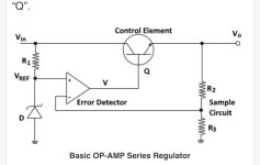
Regarding LM regulators in TO package being retired, have you considered designing regulator based on OPAMP and a transistor?
Attached is the idea what i’m thinking
0.00011% vs 0.00045%
That’s THD+N.
It would be sad to see Modulus-86 retired, as such performance will be hard to come by with other vendors.
Regarding LM regulators in TO package being retired, have you considered designing regulator based on OPAMP and a transistor?
Attached is the idea what i’m thinking
Attachments
Last edited:
Part of that is that the Modulus-286 was measured on the APx525 whereas the Modulus-86 Rev. 3.0 is measured on the APx555B. The extra $20k of the 555 on the 525 allows me to measure the true performance of the Modulus amps. I just haven't measured the Modulus-286 with the 555 yet.At first I wanted to get Modulus-286, but when I compared THD/THD+N specs I realized that Modulus-86 is superior.
0.00011% vs 0.00045%
That’s THD+N.
I could do that but it's rather overkill for the application. Currently I think the idea of standing two TO-220 versions up against each other and bolting them together has the most going for it. It's also entirely possible that I order a lifetime supply of the TO-92 version so I can keep kits going for another while.Regarding LM regulators in TO package being retired, have you considered designing regulator based on OPAMP and a transistor?
Tom
The extra $20k of the 555 on the 525 allows me to measure the true performance of the Modulus amps.
The price for those AP devices is like a yearly salary. Is there a service where people can rent those and as a result not pay the whole purchase cost?
Trust me. It was not lost on me that I just spent 2/3 of the median yearly salary for a single Canadian when I dropped off the bank draft to pay for the APx555. I didn't lose as much sleep over it as I did when I bought the APx525 years earlier, but the decision definitely weighed on me. It was one of those occasions where I muttered to myself, "I hope you know what you're doing".
Then again, test equipment has been a long-timefetish interest of mine and I make a living making low-distortion amps. I would like to be able to measure them. I tried for a few years to improve my capabilities with the APx525 using filters and such. I designed a kick-a** elliptical filter that provided 50 dB attenuation above 2 kHz with deep notches at 2 kHz and 3 kHz and hardly any attenuation of the 1 kHz fundamental in an effort to clean up the 525's signal source and a deep notch filter to null out the fundamental before it entered the analyzer. It worked great and got me down around -140 dBc ... at one specific combination of amplitude and frequency. The B-series APx555 gets me to -148 dBc (1 kHz, 2 V RMS) and is much more consistent in performance vs frequency and amplitude.
Anyway. Sure. There are rental services. It's been a while since I looked, but last I looked prices were in the thousands (plural) of dollars per week. It was definitely one of those, "yeah, no. Ain't doing that" types of things. Granted, I think they rented out the $50k model with bluetooth, HDMI, and whatnot, but it was also something like $5k/week.
Tom
Then again, test equipment has been a long-time
Anyway. Sure. There are rental services. It's been a while since I looked, but last I looked prices were in the thousands (plural) of dollars per week. It was definitely one of those, "yeah, no. Ain't doing that" types of things. Granted, I think they rented out the $50k model with bluetooth, HDMI, and whatnot, but it was also something like $5k/week.
Tom
Maybe a dumb question here but why do you need softstart for SMPS?View attachment 1248489
For the revision 3 boards I have one Intelligent Soft Start and two Guardian-86's, so a complete set of Neurochrome protection and control. I still need to buy another set for the revision 2.4 build. After import tax and shipping a set of protection and control is almost 500 euro to get it to the Netherlands, or roughly one third of the total cost to build these amplifiers if you get a nice chassis machined. The protection and control are quite a chunk of the total budget, so it's tempting to skip. I want to do it right however and build them as good as I can. There's a chance these amplifiers will get used by someone else some day and I sleep better if all precautions are included.
Most (but not all) SMPSes have built-in soft start so they might not need the soft start feature of the ISS. That said, the ISS offers many other features, including:
Tom
- Support for two types of power switches: Toggle and momentary switches. These can be low-voltage types as 3.3 V signalling is used.
- Child-protection feature, enabled by jumper, requires the momentary power button to be held for 1.5 seconds to turn on or off the power.
- Opto-isolated 12 V trigger input for power control. This input has been optimized for good noise immunity.
- Standby/Power indication using a bi-colour LED (or two individual LEDs in anti-parallel). The brightness of each LED can be set independently using two trimpots.
- +5 V always-on auxiliary power supply (100 mA, max.)
Tom
TL;DR
Finished Mod-86 amp, looks great, sounds great, great experience with Neurochrome support and with building using Neurochrome products. Highly recommended! Pictures at the end.
Thanks everyone for advising on flux cleaning and the quality of solder joints. I bought the Chemtronics flux cleaner and it made a difference of night and day. Of course my boards already had a couple of passes of isopropanol, but I could immediately feel the difference: there was almost no resistance to my ESD brush when I put a thin layer of the Chemtronics cleaner on the bottom of the board. I scrubbed the whole PCB, then rinsed thoroughly with DI water. After that, I put the boards into the oven for 10 minutes at 80 degrees C. I think I should measure the temp of my oven, it could have exceeded 80 degrees, but luckily it hasn't caused any problems.
The boards and solder joints look great now, but I didn't get a picture of the joints again before putting them into the chassis.
In the meantime, my Mod-86 rev 3 is finished! I ordered a Dissipante 2U chassis from Modushop in the evening of Monday 18 December. Modushop shipped the drilled, threaded and printed chassis on Wednesday in the same week! It even arrived before christmas from Italy to the Netherlands. I thought I would be building somewhere in January, instead the amp was finished before new years eve. Thanks a bunch to Modushop for this one!
The chassis looks great too. The only minor thing I noticed is that the middle of the back panel bends slightly when fitting an IEC connector. I placed it right in the middle of the panel too, at the weakest point. Nothing to worry about too much. Modushop is aware of this and looking for a way to improve. Communication with them is swift, kind and clear.
Another slight mistake is that the text above the left input is 1mm too high. I'll work with Modushop to get this corrected in my next build, no reason to expect more problems like this.
Like I said, the amp looks great. If I was selling a batch of 100, I'd like to get the last details perfect too. This being the third power amp chassis I dedigned and built though, the result is not shabby at all.
As mentioned in an earlier post, the setup is as follows: 2x Mod86, ISS and speaker protection, Connex SMPS300REh PSU. I thought long and hard on possible amp layouts. In the end my layout looks exactly like a whole bunch of Mod-86 builds and I believe for good reason: it's hard to improve on this layout. I put in a standby switch, standby LED (red) and power LED (green). Here was some room to get creative, so I mounted them in the bottom panel, right behind the front of the amp. This way, the LED's are not in your face (don't like that stuff at all) but you can clearly tell the status by the reflection of the LED on the amp's supporting surface. This idea turned out nice.
Currently, only the green LED works. The LED's connect to the Intelligent Soft Start (ISS). With two separate LED's, you connect them to the same two screw terminal positions on the ISS, in anti-parallel. Turns out my LED's behave rather curious for so-called diodes, they burn no matter the polarity. The result is that both LED's burn in both positions of the standby switch. For now, I fully dimmed the trim pot for the standby LED, and cut its connection, to get the green LED working correct.
I looked for a century for some nice sturdy panel mounted LED's, and found the ones I used on Amazon. I ordered some diodes to fix their behavior, still waiting on those.
In my experience, help from Tom has been exceptional, without exception. He has assisted me with the few questions I had during building and measuring. Tom's YouTube video on testing and measuring an amplifier got me started with measuring. I soldered some short plugs to short the input XLR connectors on the amp. My Brymen BM867s multimeter (which has pretty good DC sensitivity) showed around 0.5 millivolt DC at the output of one channel around 0.3 millivolt DC on the other.
Next I connected a signal generator to the amp input, with a 50 ohm terminator (am I the only one who thinks of Arnold Schwarzenegger when using these?) to a Neutrik BNC -> XLR plug. I got put off at this stage looking at the gain, as I was getting 5x the output voltage as compared to the voltage setting of the signal generator that feeds the input. Turns out the 50 ohm terminator halves it. With that thing being called a terminator, I guess I'm lucky there's any voltage left at all. Thanks to Tom for helping me to figure this out. I ended up testing with 2 V RMS in (4 V RMS on the signal generator), which gives 20 V RMS out on both channels, so a proper 10x gain. 20 V RMS divided by 8 ohm (I used a load resistor) gives 2.5 A. So 20 V times 2.5 A is around 50 watt of output. No clipping on the scope yet at this level. Note that I used a ±36 V PSU, not recommended by Tom, to get more than 40 watt available.
I let each channel run for about 15 minutes at 50 watt. Checking the temperature around the chassis and around the heat sink, the hottest point on both sides is between the LM3886 and the middle of the heat sinks. The hottest point got to around 70 degrees C. The outside of the heat sink could still be touched but feels quite hot at this stage. Of course this is (almost) max power of this build, and using sine wave, not music. So for actual use everything is great.
I'm learning all of this as I go, and one thing kinda scared me: the temperature of my load resistor got above 130 degrees C. I don't like having metal objects inside my house that get so hot. It's a regular 8 ohm 100 watt aluminum dummy resistor. Wasn't expecting the resistor to get so hot after loading it for 30 minutes with half of its max rating.
Can anybody advise on a proper load for testing amplifiers? I'd like to be able to test 4 ohm and 8 ohm, up to about 250 watt (thinking about amps like the Mod-686 and some Hypex or Purifi in the future). I saw a nice programmable load from Quantasylum for a decent price, but it only goes to 200 watt and that's peak. Certainly not enough for the stress tests I want to do.
I can share some lessons learned from this build that are top of mind right now:
With all that said, let's get to listening and photos. A year ago, my system consisted of a pair of Mission M74i floorstanders + B1 buffer (preamp) + LM3886DR (power amp) + logitech bluetooth unit. The bluetooth unit recently got replaced with a fanless HTPC (Windows with Roon) and an SMSL D-6s DAC (with volume control, so the DAC goes straight to a power amp). I also moved from Spotify to Tidal HiFi Plus. With the source updated to the current decennium, all high quality and high performance, the power amp deserved some love, hence the Mod-86. The speakers are still pretty good (subjectively, got no clue otherwise).
With placing the Mod-86 in my system, I've also connected a Wiim Pro Plus instead of the PC + DAC. I want to get into PEQ (never done it before). The Wiim is a bit behind the SMSL DAC but in the same league. I wanted to test it anyway, to loan to friends together with future amps I'll build. The app is nicely integrated with support for a whole bunch of stuff. Eventually I want PEQ measured with Acourate and implemented with CamillaDSP. The Wiim together with the iPhone app House Curve are my first EQ and DSP training wheels.
To be honest, I just like listening to music. If you'd cast a spell so I couldn't upgrade the system I had last year anymore, I could live with that. Upgrading the source was a night and day difference though, it really struck me and everyone who's heard it, still with the LM3886 in the system. With the Mod-86 connected, I got more of the same improvement as when I upgraded the source. Everything just cleans up so much. A whole lot of separation between instruments, and bass much more tightly controlled. The Mod-86 deserves a whole lot more listening time than I've put in at this moment, so I'll share a more detailed experiences later on.
I'll try to attach some pictures. They include:
Next, I'll be trying to complete an amp with the Mod-86 rev 2.4 boards I've still got.
Finished Mod-86 amp, looks great, sounds great, great experience with Neurochrome support and with building using Neurochrome products. Highly recommended! Pictures at the end.
Thanks everyone for advising on flux cleaning and the quality of solder joints. I bought the Chemtronics flux cleaner and it made a difference of night and day. Of course my boards already had a couple of passes of isopropanol, but I could immediately feel the difference: there was almost no resistance to my ESD brush when I put a thin layer of the Chemtronics cleaner on the bottom of the board. I scrubbed the whole PCB, then rinsed thoroughly with DI water. After that, I put the boards into the oven for 10 minutes at 80 degrees C. I think I should measure the temp of my oven, it could have exceeded 80 degrees, but luckily it hasn't caused any problems.
The boards and solder joints look great now, but I didn't get a picture of the joints again before putting them into the chassis.
In the meantime, my Mod-86 rev 3 is finished! I ordered a Dissipante 2U chassis from Modushop in the evening of Monday 18 December. Modushop shipped the drilled, threaded and printed chassis on Wednesday in the same week! It even arrived before christmas from Italy to the Netherlands. I thought I would be building somewhere in January, instead the amp was finished before new years eve. Thanks a bunch to Modushop for this one!
The chassis looks great too. The only minor thing I noticed is that the middle of the back panel bends slightly when fitting an IEC connector. I placed it right in the middle of the panel too, at the weakest point. Nothing to worry about too much. Modushop is aware of this and looking for a way to improve. Communication with them is swift, kind and clear.
Another slight mistake is that the text above the left input is 1mm too high. I'll work with Modushop to get this corrected in my next build, no reason to expect more problems like this.
Like I said, the amp looks great. If I was selling a batch of 100, I'd like to get the last details perfect too. This being the third power amp chassis I dedigned and built though, the result is not shabby at all.
As mentioned in an earlier post, the setup is as follows: 2x Mod86, ISS and speaker protection, Connex SMPS300REh PSU. I thought long and hard on possible amp layouts. In the end my layout looks exactly like a whole bunch of Mod-86 builds and I believe for good reason: it's hard to improve on this layout. I put in a standby switch, standby LED (red) and power LED (green). Here was some room to get creative, so I mounted them in the bottom panel, right behind the front of the amp. This way, the LED's are not in your face (don't like that stuff at all) but you can clearly tell the status by the reflection of the LED on the amp's supporting surface. This idea turned out nice.
Currently, only the green LED works. The LED's connect to the Intelligent Soft Start (ISS). With two separate LED's, you connect them to the same two screw terminal positions on the ISS, in anti-parallel. Turns out my LED's behave rather curious for so-called diodes, they burn no matter the polarity. The result is that both LED's burn in both positions of the standby switch. For now, I fully dimmed the trim pot for the standby LED, and cut its connection, to get the green LED working correct.
I looked for a century for some nice sturdy panel mounted LED's, and found the ones I used on Amazon. I ordered some diodes to fix their behavior, still waiting on those.
In my experience, help from Tom has been exceptional, without exception. He has assisted me with the few questions I had during building and measuring. Tom's YouTube video on testing and measuring an amplifier got me started with measuring. I soldered some short plugs to short the input XLR connectors on the amp. My Brymen BM867s multimeter (which has pretty good DC sensitivity) showed around 0.5 millivolt DC at the output of one channel around 0.3 millivolt DC on the other.
Next I connected a signal generator to the amp input, with a 50 ohm terminator (am I the only one who thinks of Arnold Schwarzenegger when using these?) to a Neutrik BNC -> XLR plug. I got put off at this stage looking at the gain, as I was getting 5x the output voltage as compared to the voltage setting of the signal generator that feeds the input. Turns out the 50 ohm terminator halves it. With that thing being called a terminator, I guess I'm lucky there's any voltage left at all. Thanks to Tom for helping me to figure this out. I ended up testing with 2 V RMS in (4 V RMS on the signal generator), which gives 20 V RMS out on both channels, so a proper 10x gain. 20 V RMS divided by 8 ohm (I used a load resistor) gives 2.5 A. So 20 V times 2.5 A is around 50 watt of output. No clipping on the scope yet at this level. Note that I used a ±36 V PSU, not recommended by Tom, to get more than 40 watt available.
I let each channel run for about 15 minutes at 50 watt. Checking the temperature around the chassis and around the heat sink, the hottest point on both sides is between the LM3886 and the middle of the heat sinks. The hottest point got to around 70 degrees C. The outside of the heat sink could still be touched but feels quite hot at this stage. Of course this is (almost) max power of this build, and using sine wave, not music. So for actual use everything is great.
I'm learning all of this as I go, and one thing kinda scared me: the temperature of my load resistor got above 130 degrees C. I don't like having metal objects inside my house that get so hot. It's a regular 8 ohm 100 watt aluminum dummy resistor. Wasn't expecting the resistor to get so hot after loading it for 30 minutes with half of its max rating.
Can anybody advise on a proper load for testing amplifiers? I'd like to be able to test 4 ohm and 8 ohm, up to about 250 watt (thinking about amps like the Mod-686 and some Hypex or Purifi in the future). I saw a nice programmable load from Quantasylum for a decent price, but it only goes to 200 watt and that's peak. Certainly not enough for the stress tests I want to do.
I can share some lessons learned from this build that are top of mind right now:
- There's almost no distance between the nut on the bolt of the feet and the side support of the inner plate. I thought I had more room, got lucky things fit
- Using the inner plate in a 2U chassis gives you about 70mm of available height in the rest of the chassis. I cut it close with my chosen orientation of the speaker protection. The output wiring (bottom in my build) can only be connected by removing the speaker protection PCB from the chassis
- I was trying to use Canare star quad speaker cable for the output wiring: way too thick. I ended up using the same wiring as I used for the AC and DC connections. It's pure copper, strands combining to a 1.5mm2 wire (between 15 and 16 AWG). Nothing wrong with that, but aesthetically it would be cooler to have some Mogami or Canare wiring here
- The input wiring uses the Canare star quad microphone cable (L-4E6S). That's also too thick actually, but a bit easier to get it to fit. I might go to the regular version of this for my next build (so 2 wires plus shield instead of the 4 wires plus shield the star quad version has). I think the outer diameter is a bit more than 8mm for this cable. The connections are mostly OK with the cables tied down, but still a tiny bit more stress on the connectors than I'd like. With a bit more flexibility, the cable length and position could also be a bit tighter than in this build
- I didn't have any nice wire thinner than 1.5mm2 for the low voltage connections (LED's and standby switch). I used the same wire as for the PSU connections. It's not really nice. The 1.5mm2 wire I have on 100 meter spools. What would be a good thickness for low voltage DC wiring? I'll buy some more spools for my next build
- Installing things on the bottom panel made for an interesting order of operations during the building process. I was forced to use something like screw terminals to disconnect the bottom panel connections relatively quick, otherwise things get really impractical. I'd like to have some nicer connectors for this, maybe something like the oldschool hard disk molex connector in PC cases before SATA became a thing
With all that said, let's get to listening and photos. A year ago, my system consisted of a pair of Mission M74i floorstanders + B1 buffer (preamp) + LM3886DR (power amp) + logitech bluetooth unit. The bluetooth unit recently got replaced with a fanless HTPC (Windows with Roon) and an SMSL D-6s DAC (with volume control, so the DAC goes straight to a power amp). I also moved from Spotify to Tidal HiFi Plus. With the source updated to the current decennium, all high quality and high performance, the power amp deserved some love, hence the Mod-86. The speakers are still pretty good (subjectively, got no clue otherwise).
With placing the Mod-86 in my system, I've also connected a Wiim Pro Plus instead of the PC + DAC. I want to get into PEQ (never done it before). The Wiim is a bit behind the SMSL DAC but in the same league. I wanted to test it anyway, to loan to friends together with future amps I'll build. The app is nicely integrated with support for a whole bunch of stuff. Eventually I want PEQ measured with Acourate and implemented with CamillaDSP. The Wiim together with the iPhone app House Curve are my first EQ and DSP training wheels.
To be honest, I just like listening to music. If you'd cast a spell so I couldn't upgrade the system I had last year anymore, I could live with that. Upgrading the source was a night and day difference though, it really struck me and everyone who's heard it, still with the LM3886 in the system. With the Mod-86 connected, I got more of the same improvement as when I upgraded the source. Everything just cleans up so much. A whole lot of separation between instruments, and bass much more tightly controlled. The Mod-86 deserves a whole lot more listening time than I've put in at this moment, so I'll share a more detailed experiences later on.
I'll try to attach some pictures. They include:
- Front and back of the amp
- Overviews of amp guts and wiring
- Close-ups: ISS + PSU, left and right channel, LED and standby switch connections, signal generator, scope measurement
- Details of bottom-mounted LED's and switch
- Temperature measurement
- Overview of measurement setup
- DC measurements
- Amp in its natural habitat (photo of the whole system will follow when I have daylight)
Next, I'll be trying to complete an amp with the Mod-86 rev 2.4 boards I've still got.
Attachments
-
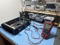 Photo 30-12-2023, 22 21 36.jpg668.1 KB · Views: 110
 -
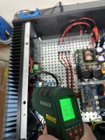 Photo 30-12-2023, 22 51 41.jpg409.3 KB · Views: 107
 -
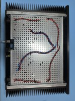 Photo 29-12-2023, 13 32 58.jpg654.4 KB · Views: 105
 -
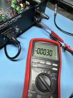 Photo 30-12-2023, 00 13 50.jpg592.3 KB · Views: 94
 -
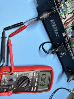 Photo 30-12-2023, 00 15 16.jpg574.4 KB · Views: 106
 -
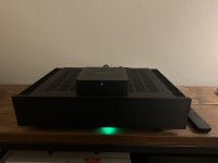 Photo 03-01-2024, 19 05 55.jpg360.6 KB · Views: 101
 -
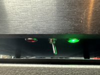 Photo 30-12-2023, 23 05 39.jpg426.1 KB · Views: 104
 -
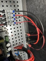 Photo 30-12-2023, 23 05 00.jpg700.9 KB · Views: 106
 -
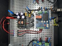 Photo 30-12-2023, 23 02 06.jpg650.3 KB · Views: 109
 -
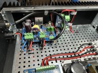 Photo 30-12-2023, 23 01 52.jpg729.1 KB · Views: 110
 -
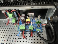 Photo 30-12-2023, 23 01 37.jpg692.8 KB · Views: 107
 -
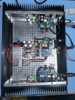 Photo 30-12-2023, 22 24 16.jpg656 KB · Views: 110
 -
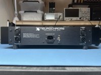 Photo 30-12-2023, 23 03 33.jpg369.2 KB · Views: 105
 -
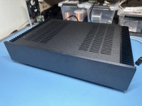 Photo 30-12-2023, 23 09 46.jpg360.1 KB · Views: 101
 -
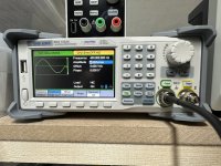 Photo 30-12-2023, 22 59 09.jpg550.5 KB · Views: 87
 -
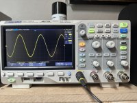 Photo 30-12-2023, 22 59 28.jpg531.4 KB · Views: 109
- Home
- Amplifiers
- Chip Amps
- Modulus-86 build thread