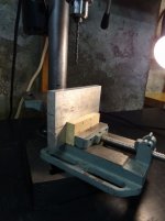
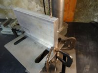
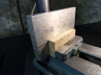
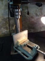
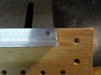
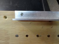
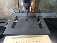
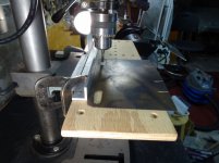
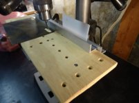
Here are two different heat sink drilling setups. The second setup uses two parallel bars and five C clamps with the 5th acting as a positioning stop for the heat sink. Use your hand to apply downward and towards the stop pressure on the heat sink while drilling to keep the heat sink against the stop.
Attachments
-
 DSC00645drilling heat sink1.JPG106.3 KB · Views: 274
 -
 DSC00650drilling heat sink6.JPG120.8 KB · Views: 116
 -
 DSC00649drilling heat sink5.JPG97.9 KB · Views: 270
 -
 DSC00648drilling heat sink4.JPG139.9 KB · Views: 263
 -
 DSC00647drilling heat sink3.JPG117.1 KB · Views: 272
 -
 DSC00646drilling heat sink2.JPG100 KB · Views: 280
Tom:
Many thanks. I knew about drill press hold-downs but will do a bit more research to select ones that fit on my relatively small drill table.
As I suspected, not any really great way to make the IEC cut-out. I've used the small hole method, but using a Dremel tool with the cut-away saw blade (rwearing protective glasses is a MUST) to cut between the holes; this is followed - as you note - by the file. OK for aluminum; I'm not going to use a file on steel (lucky thing most panels are aluminum).
Geary
I've used the "small holes" method to make the hole for an IEC inlet in 1 mm steel. It works just fine. It just takes longer.")
Tom
Your nickname should be Tom "the Arm," given how difficult it is to file steel.
Upon reflection, I think I will try to use some kind of grinder - perhaps the Dremel again with a cylindrical grinding stone or sanding cylinder. I wish I had enough knowledge to use a trim router - that might do the trick.
The trick with filing is to apply pressure and go slowly. So press down on the file and move it back and forth somewhat slowly and deliberately. I don't think it took me more than 20 minutes to drill, punch, and file the hole.
Now, this does require that the edge of the holes line up with the edge that you want so all you need to do is to file the bits of metal that the drill bit didn't remove. If you have to remove more than maybe 0.5 mm life will suck for a while.
Tom
Now, this does require that the edge of the holes line up with the edge that you want so all you need to do is to file the bits of metal that the drill bit didn't remove. If you have to remove more than maybe 0.5 mm life will suck for a while.
Tom
Size of holes in-line
OK, I see that there may be two possible problems with my approach in the past:
1. I am drilling too large holes in-line and not drilling them closely enough together. It seems I should be using a relatively small bit - like 1/16" or smaller - and then drilling them very close together so that it looks somewhat like the perforations in paper that are used for "tear-off" portions of the sheet. Probably four larger holes will have to be filled to get the saw blade in (unless I use the Dremel), and then that leaves very little for the file to remove.
2. I am not using the saw to cut as close as possible to the outside edge of the line of holes, thereby leaving only a residual amount of metal to remove.
What do you think?
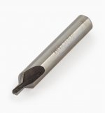
I find a small drill bit tends to wander too much. Maybe a small centering drill would work.
For the steel panel I mentioned I used a 4 mm drill bit and placed the holes as close together as I could. It was a bit of a chore to get the middle punched out but with a small round file and some gentle prying with a small screwdriver I was able to break the bits of metal between the holes. It doesn't have to be pretty. As long as you don't distort the panel you're fine. You then make it pretty with a file after.
If you have a Dremmel I would imagine that you can find a bit that'll work for breaking the connections between the holes.
Tom
Attachments
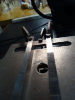
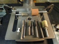
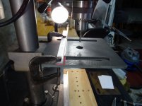
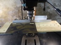
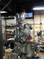
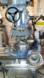
Occasionally I’ve used my drill press for deburring. And while drill press spindle bearings are not optimal for side loads I’ve had no problems. The setup is simple and only requires two pieces of angle iron or any straight edge, a flat piece of wood and three C clamps. To make the part holding fixture secure the straight edge to the piece of wood. C clamps would work but drilling a hole near each end so it could be screwed to the piece of wood is neater. Two clamps will secure a straight edge to the drill table and one clamp will secure the fixture to the drill table. The fixture does not require any special alignment.
The following process replaces only the filing with light deburring.
Secure the cutting tool in the chuck. Place one straight edge on the drill table. Position the back edge of the fixture against that straight edge Place the piece to be deburred on the fixture with one edge against the fixture straight edge and move everything together such that the end of the cutter is the very close to the edge to be deburred. Raise the table until the end of the cutting tool just touches the wood. Lock the table in place.
Use two C clamps to secure the table straight edge. Secure the fixture to the table with one C clamp at either the left or right side.
Think of the clamped side of the fixture, where it contacts the table straight edge, as a pivot point. So slightly loosening the clamp and pulling the other side of the fixture away from the table straight edge is like a very slight rotation that increases the depth of the cut.
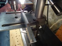
With the fixture against the table straight edge slightly loosen the fixture C clamp and pull the other side of the fixture away from the table straight edge to bring the highest point of the edge to be deburred in contact with the cutter. Only make very light cuts. Now tighten the fixture C clamp and slide the part, along the straight edge, to a position where the cutter is not in contact with the edge to be deburred. While holding down the work piece, start the spindle and slowly slide the work piece back and forth until the cutter is no longer removing anything. The first pass is now done.
Now, with the cutter still running, slightly loosen the fixture clamp and gently pull the other side of the fixture away from the table straight edge to take a light chip about the thickness of a business card then place the card between the table straight edge and back of the fixture. Push that side of the fixture against the card/shim and tighten the fixture C clamp and repeat the material removal process as before. Repeat the process adding business cards or any other shim material for subsequent passes. Repeat this process until the edge is as smooth as you like.
The following process replaces only the filing with light deburring.
Secure the cutting tool in the chuck. Place one straight edge on the drill table. Position the back edge of the fixture against that straight edge Place the piece to be deburred on the fixture with one edge against the fixture straight edge and move everything together such that the end of the cutter is the very close to the edge to be deburred. Raise the table until the end of the cutting tool just touches the wood. Lock the table in place.
Use two C clamps to secure the table straight edge. Secure the fixture to the table with one C clamp at either the left or right side.
Think of the clamped side of the fixture, where it contacts the table straight edge, as a pivot point. So slightly loosening the clamp and pulling the other side of the fixture away from the table straight edge is like a very slight rotation that increases the depth of the cut.
With the fixture against the table straight edge slightly loosen the fixture C clamp and pull the other side of the fixture away from the table straight edge to bring the highest point of the edge to be deburred in contact with the cutter. Only make very light cuts. Now tighten the fixture C clamp and slide the part, along the straight edge, to a position where the cutter is not in contact with the edge to be deburred. While holding down the work piece, start the spindle and slowly slide the work piece back and forth until the cutter is no longer removing anything. The first pass is now done.
Now, with the cutter still running, slightly loosen the fixture clamp and gently pull the other side of the fixture away from the table straight edge to take a light chip about the thickness of a business card then place the card between the table straight edge and back of the fixture. Push that side of the fixture against the card/shim and tighten the fixture C clamp and repeat the material removal process as before. Repeat the process adding business cards or any other shim material for subsequent passes. Repeat this process until the edge is as smooth as you like.
Attachments
-
 DSC00653drilling as miller2.JPG147.6 KB · Views: 82
 -
 DSC00669drilling as miller8.JPG122.1 KB · Views: 85
 -
 DSC00668drilling as miller7.JPG119.9 KB · Views: 83
 -
 DSC00667drilling as miller6.JPG130.6 KB · Views: 86
 -
 DSC00666drilling as miller5.JPG133.7 KB · Views: 80
 -
 DSC00665drilling as miller4.JPG134.5 KB · Views: 85
 -
 DSC00664drilling as miller3.JPG137.1 KB · Views: 85
 -
 DSC00663drilling as miller2.JPG110.7 KB · Views: 98
 -
 DSC00662drilling as miller1.JPG128.5 KB · Views: 83
Great Photos
@heryrljr:
Thank you for your explanation and especially the time you took to take the photos! I am looking very carefully at the photos and now can grab your approach, which is very clever. Thank you so much for this.
I feel that DIY should put together some kind of guide to chassis making and metalworking. I'd be willing to help pitch in, something analogous to the build guides.
Henry: That's an excellent method. Thanks for sharing. It seems 99% of machine shop work is setting up the jigs.
And I'd like to point out that if you don't have a drill press, a drill stand can be had for not that much money. It does require that your power drill has a collar that can go into the stand, though. The chassis work I did in my teens was all done on my dad's drill stand.
Tom
And I'd like to point out that if you don't have a drill press, a drill stand can be had for not that much money. It does require that your power drill has a collar that can go into the stand, though. The chassis work I did in my teens was all done on my dad's drill stand.
Tom
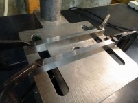
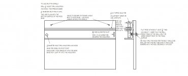
While I usually do most work on my bridgeport, if I only had a drill press this is how the fixture would look. By using split pin dowels and the wing nuts, including two on the 1/4-20 adjustment screw no tapping is required and no wrenches are needed. The hole for the adjustment screw may need to be closer to the top edge of the angle iron to allow use of wing nuts.
Attachments
Great. Now I have milling machine envy... It's probably a good thing I don't have the shop space for one.
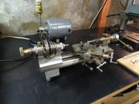
I have been drooling over Sherline's milling machines for a few years, though: https://www.sherline.com
They'll fit on a table top. I did once machine a 19" front panel on one of those. It was a bit of a chore as the table is only 12" but I got the job done.
Tom
It's probably a good thing I don't have the shop space for one.I have been drooling over Sherline's milling machines for a few years, though: https://www.sherline.com
They'll fit on a table top. I did once machine a 19" front panel on one of those. It was a bit of a chore as the table is only 12" but I got the job done.
Tom
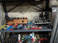
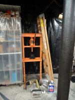
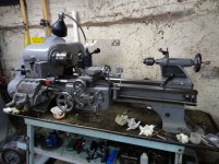
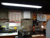
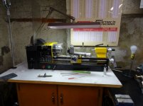
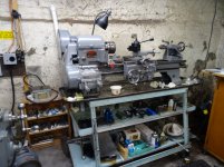
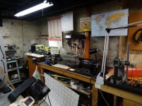
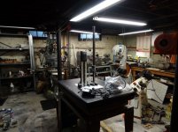
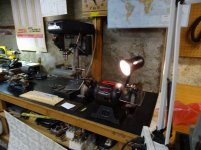
This is my playground. Well it was actually a home business where I did repair and custom work in all metals from A to Z, as in zirconium. I also designed, made and sold a few titanium clarinet tuning barrels and flute stoppers in titanium, niobium and zirconium. I also did design and make of prototypes working with folks with ideas for a patent. I mention this because I still except accept small, interesting jobs. I charge $30 per hour + cost of raw material and cutting tools.
Attachments
-
 DSC00681machine shop equip12.JPG177.5 KB · Views: 94
 -
 DSC00680machine shop equip11.JPG99.1 KB · Views: 105
 -
 DSC00679machine shop equip10.JPG186.4 KB · Views: 97
 -
 DSC00678machine shop equip9.JPG141.3 KB · Views: 101
 -
 DSC00677machine shop equip8.JPG142.1 KB · Views: 101
 -
 DSC00676machine shop equip7.JPG143.2 KB · Views: 106
 -
 DSC00675machine shop equip6.JPG182.6 KB · Views: 105
 -
 DSC00674machine shop equip5.JPG172.5 KB · Views: 218
 -
 DSC00670machine shop equip1.JPG162.8 KB · Views: 214
 -
 DSC00686machine shop equip17.JPG160.5 KB · Views: 96
For those needing super accurate work, my granite surface plate is flat wi/in .00005 based on calibration. I have dial indicators with divisions from .001 to .00005. Its just a bunch of great toys. And I have compound and single leaf sine plates accurate wi/in .0002. I've done several jobs for one of the largest aerospace companies, more than $30, requiring tight tolerances.
- Home
- Amplifiers
- Chip Amps
- Modulus-86 build thread