another good calculator
I just found this calculator with many variable inputs and
lots of calculated outputs. Heatscape Homepage.
Yeah. It seems pretty solid. It would be nice if it could handle serrated fins
Tom
I just found this calculator with many variable inputs and
lots of calculated outputs. Heatscape Homepage.
I just noticed what may point to a problem with the heat sink I'm considering. I'm running the calculators for a 184W x 48H x 117L, 23 fin fin t3 b5 heat sink. The Heat Sink Size Calculator takes a Ts max temp. input and I entered 65 C. it returned info that a 162mm wide with 17 fins would work. So I thought the heat sink would work with the LM4780.
I entered same info, but it dosen't accept a Tsmax, in the Heatsink Calculator, Natural Convection and it returned JC temp. of 141.4. That's a big difference and based on the 141.4C it would seem the heat sink should not be used with the LM4780. Any thoughts on that would be appreicated.
I entered same info, but it dosen't accept a Tsmax, in the Heatsink Calculator, Natural Convection and it returned JC temp. of 141.4. That's a big difference and based on the 141.4C it would seem the heat sink should not be used with the LM4780. Any thoughts on that would be appreicated.
here is heat sink size calculator input and results:
Tamb:25 °C
Ts (max):65 °C
P:50 Watts
L:117 mm
H:48 mm
b:5 mm
t:3 mm
Emissivity:.86
Calculation results:
W: 162 mm
s: 6.94mm
Number of fins:17
Here is Heatscape Calculator, Natural Convection results with the same inputs:
Case Temperature of 1st Heat Source ˚C101.4
Junction Temperature of 1st Heat Source ˚C141.4.
Is the thermal resistance, of this heat sink, to high to be used in the Parallel 86 amp.?
That Heatscape calculator is excellent. Very nice find. Thank you for sharing!
The calculator seems to take the heat sink dimensions, locations of the heat sources, dissipated power, and calculate the thermal resistance of the heat sinks from there. I'm not seeing a calculator that allowed for the heat sink dimensions to be calculated from the thermal resistance (or temperature, power specs). Would you share a link for that one?
With the Parallel-86, you're looking at 50 W dissipated in the LM4780 for music signal at clipping with a 4 Ω load. 29 W for an 8 Ω load under the same conditions.
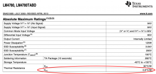
Which values did you use for the TIM (Thermal Interface Material) thickness and thermal resistance? Did you use the correct values for the thermal resistance of the LM4780 package? I would set Theta JB to a large value (say 100) as you're not conducting heat through the package to the PCB.
Tom
The calculator seems to take the heat sink dimensions, locations of the heat sources, dissipated power, and calculate the thermal resistance of the heat sinks from there. I'm not seeing a calculator that allowed for the heat sink dimensions to be calculated from the thermal resistance (or temperature, power specs). Would you share a link for that one?
With the Parallel-86, you're looking at 50 W dissipated in the LM4780 for music signal at clipping with a 4 Ω load. 29 W for an 8 Ω load under the same conditions.
Which values did you use for the TIM (Thermal Interface Material) thickness and thermal resistance? Did you use the correct values for the thermal resistance of the LM4780 package? I would set Theta JB to a large value (say 100) as you're not conducting heat through the package to the PCB.
Tom
Running heatscape as before, except for inputting 100 for JB, returned junction temp. of 133.2. the previous run inputting 0 for JB returned junction temp. of 141.4. Am I not understanding something? Does the other heat sink calculator that accepts a max junction temp, where I enter 65, actually base results on the junction temp.not exceeding 65˚C
Heat Sink Size Calculator should get you to the calculator that accepts T amb, Ts max, length, height, base thickness and fin thickness and returns total width, fin spacing and number of fins that would keep the maximum heat source temperature from exceeding 65˚C.
Last edited:
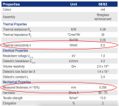
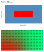
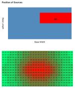
I plugged in your numbers. I used the dimensions of the LM4780 as the heat source size and placed it centred on the heat sink. I used the properties of the Keratherm Red thermal interface material for the TIM parameters. I had to increase the Theta-JB to 1000 to eliminate the power dissipated into the PCB.
The results are spot on with the design requirements. At 25 ºC ambient the heat sink reaches 65 ºC with 50 W dissipated in it.
The junction temperature of the LM4780 comes out to 121 ºC. The chip is rated for operation up to 150 ºC. You may have to right click the last image and select "open in new tab" to be able to read the numbers.
I don't see the problem.
The only issue I see is that the heat sink calculator assumes all the power dissipated by the heat source is dissipated at its lower left corner. That's annoying. That's why the left and right sides of the heat sink are at different temperatures. They should be identical. But ya know... For a free tool I think you get *a lot* of value.
Tom
Attachments


In the package section of the calculator the X and Y location can be entered. It has worked well in the many runs I've done.
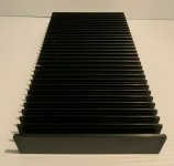
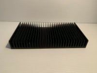
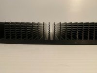
And based on results I finally bought a heat sink. The junction temp will be 114.3 and the hot spot temp will be 71ºC. The heat sink C/W will probably be lower based on the wavy fins. The length is 6.375 but I entered 80mm for length because I will be cutting it in half to result in two usable heat sinks.
And based on results I finally bought a heat sink. The junction temp will be 114.3 and the hot spot temp will be 71ºC. The heat sink C/W will probably be lower based on the wavy fins. The length is 6.375 but I entered 80mm for length because I will be cutting it in half to result in two usable heat sinks.
Attachments
Thanks Tom. The TIM inputs I used are based on a thermal grease.
Ah. That makes sense. Note that the back of the LM4780 is connected to VEE, so you do need a thermal pad there.
To bad the calculator doesn't allow turning off the PCB section.
Yeah. On the other hand, it's a free tool.
In the package section of the calculator the X and Y location can be entered. It has worked well in the many runs I've done.
I know. But the calculator assumes all the heat is dissipated at the lower left corner of the heat source, even if the heat source is the same size as the heat sink. I would rather that it assumed the heat source was isothermal.
I'm willing to work with the shortcomings given the cost of the tool. Ultimately I don't care if the edge of the heat sink is 63 ºC or 65 ºC. I can't guarantee that my living room is 25.000000000 ºC either.
")
The heat sink C/W will probably be lower based on the wavy fins.
Guaranteed! It's all about air flow and surface area.
Tom
So the heatsink calculator returns a graphic representation of the temps on the heat sink. When I center the package the graphic displays red in the center. When I position the package at the lower left corner the graphic displays red at that location. When I position the package at lower right the red shows up there. How did you determine the calculator assumes the heat is dissipated at the lower left corner of the heat source.
Weird. I just tried on Chrome to see if it was a browser issue. Same result.
Oh, well. I'll discuss with HeatScape. Bug or no bug, whatever the difference is inconsequential for a Parallel-86 build. It's not like we're building a space shuttle here... There's no reason to continue beating this particular dead horse in this thread.
Thanks for mentioning the calculator, though. That'll be very useful.
Tom
Oh, well. I'll discuss with HeatScape. Bug or no bug, whatever the difference is inconsequential for a Parallel-86 build. It's not like we're building a space shuttle here...
There's no reason to continue beating this particular dead horse in this thread.Thanks for mentioning the calculator, though. That'll be very useful.
Tom
Last edited:
OK. So on to a different topic. Seems a number of builders say they are not comfortable working with metal, like tapping holes. Well there are a few simple options.
Small diameter drills are available in four to six inch lengths. So, for example, heatsink length + bottom cover thickness just under six inches can be secured by using a 6” long drill. Position the heatsink in the desired location on the bottom cover and just drill holes through the length of the heat sink and the bottom cover. Then use long screws, washers and locknuts to secure the heat sink to the bottom cover. If sufficiently long screws cannot be found, just counter bore holes with a larger diameter drill such that screw heads will fit in the holes.
A chip can be secured to a heat sink using a clip without tapping. If a heat sink fin spacing is such that a 4-40 screw lock washer or larger will fit between the fins, the appropriate sized hole, centered between the fins, can be drilled through the heat sink. A screw, lock washer and nut can be used to secure the clip/chip to the heat sink.
Another option is using pop rivets, but the screws, washers and nuts allow easier disassembly.
Metal working issues
Some of the issues I have had:
1. How does one safely secure the piece being drilled to the drill press table - or otherwise prevent it from moving, without drilling holes through it or otherwise marring the finished surface?
2. How does one accurately locate a hole in the front panel, to coincide with a hole in a L-piece of metal holding a with or pot in the chassis, such that one can use an extension rod?
3. How does one accurately and easily cut the rectangular hole for an IEC chassis mount socket? This is the primary reason that I have gone to Neutrik PowerCon, but I still have some integrated IEC chassis mount socket and RFI filter (Corcom, etc). that I would like to use.
1. How does one safely secure the piece being drilled to the drill press table - or otherwise prevent it from moving, without drilling holes through it or otherwise marring the finished surface?
Ideally by clamping it to the table. The slots in the table are for T-nuts. You can get a clamp specifically for that purpose. Then put a piece of wood between the clamp and the workpiece to prevent scratches.
Or do what I do (and am probably not supposed to do) and hand-hold it.
Here's a slow-paced video on the topic: drill press clamps - YouTube
2. How does one accurately locate a hole in the front panel, to coincide with a hole in a L-piece of metal holding a with or pot in the chassis, such that one can use an extension rod?
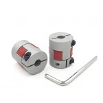
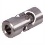
If you know the pot's location on the bracket and the bottom plate's position on the front panel, you should be able to get the hole in the right spot. But, of course, that depends on how precise the chassis is. Some vendors (ModuShop for example) provide quite a bit of slop in the assembly, so you could be off by 0.5-1 mm if you're not careful. Other vendors offer more precision, but it's probably one of those cases where "you can't get there from here". So plan for imprecision. If you're pretty darn close, you can use a flexible shaft coupling. If you're off by several mm, you'll probably have to use a cardan joint. See attached images.
3. How does one accurately and easily cut the rectangular hole for an IEC chassis mount socket?
Two methods:
- Drill a hole in each corner and use a coping saw with a metal-cutting blade to cut the rectangle. File the edges smooth.
- Drill a bunch of reasonably small holes (4-5 mm diameter) along the perimeter of the desired shape. Place the holes as close to each other as possible. Use a file to 'connect' the holes and poke out the centre. Then file the edges smooth.
BTW, you can get some excellent hole saws for cutting larger holes. I've used one made of HSS steel, but they're available with carbide tips as well. They're $10-12 at Bezos' Bookstore. Those are great for holes for XLR connectors and such.
Tom
Attachments
Most bench top drill presses have only three inches of spindle travel, meaning holes can't be drilled deeper than three inches. However most chucks accept about 1 3/4" of the drill shank. So start with the shank inserted all the way into the chuck and drill three inches deep. Then loosen the chuck and pull the shank out such that about 1/2"" length of the shank is inside the chuck jaws. Now lock the chuck and drill a hole 4 1/4" deep hole.
- Home
- Amplifiers
- Chip Amps
- Modulus-86 build thread