Well, it seems a more uniform or gradual change of cross section of higher current path is better, one of the reasons I try to avoid connectors on the PCB in these areas.
So somehow output connections of amplifiers do not follow Ohm's Law? That's news to me.
Besides, I think you missed the main point: By clever layout, I ensure to minimize the voltage drop across the output trace. In addition, also by clever layout, I ensure that whatever little drop is there is corrected for by the feedback loop of the amp.
Tom
For the Modulus-86 it's THD (no +N).
Tom
This is the plot I was looking at:
https://www.neurochrome.com/wp-cont...HDN-vs-Output-Power-8-ohm-1-kHz-BW-22-kHz.png
and the 686 plot is the first one on post #1 of this thread.
I'm still seeing the Modulus-686 as better than the Modulus-86. Reading from the two plots you mention:
@ 10 mW:
MOD86: 0.015 %
MOD686: 0.007 %
@ 1 W:
MOD86: 0.0015 %
MOD686: 0.0008 %
@ 40 W:
MOD86: 0.0004 %
MOD686: 0.0003 %
I can't find a single data point where the MOD686 is worse than the MOD86.
You can argue that the curve for the MOD686 is bumpier than that of the MOD86. That's reflective of the stellar performance of the MOD686 as well. The bumps in the low THD+N levels occur when the APx525 changes range and its noise floor jumps a bit.
Basically the THD+N plot of the MOD686 shows the noise of the MOD686 and APx525 source along with the residual THD of the APx525 source.
The difference in THD+N between the MOD86 and MOD686 is caused by the lower noise floor of the Modulus-686. The '686 should also have slightly lower THD (no +N), but at this point I am not able to measure the raw THD with enough precision to determine that for sure.
Tom
Last edited:
Gold on card edge connectors is referred to as "Hard Gold". It is thicker than ENIG but is unsuitable for soldering. You can, if you want, use it on your PCB order but there is no good reason to do so.
In the amounts deposited on PCBs, including on edge connectors, there is very little actual metal involved ... an ounce of gold can be rolled into a sheet of 100 ft2 area.
You can buy 24kt Gold Leaf @ 5 microns, which is roughly equivalent in thickness to the amounts deposited for electronics use on connectors and PCBs, 100 1.5" x 1.5" sheets, for $10. Or 25 3x3" sheets of 12 micron for $40. From that you can see that very little gold metal is deposited on a PCB or a connector, either by weight or by cost.
There is no waste material as any gold can be recovered from any solution.
It is also very heavy ... when you see guys in the movies putting gold bars into a suitcase, start laughing. A single standard 400 troy ounce gold bar (the size banks will use, at about 10" long and 3 x 1.5" wide and thick) weighs almost 30 pounds.
Last edited:
Modulus-686: 380W (4Ω); 220W (8Ω) Balanced Composite Power Amp with extremely low THD
Regardless for whatever reason, could we not use the the connectors but solder wires directly to the board? And what size wires can be used?
So somehow output connections of amplifiers do not follow Ohm's Law? That's news to me.
Besides, I think you missed the main point: By clever layout, I ensure to minimize the voltage drop across the output trace. In addition, also by clever layout, I ensure that whatever little drop is there is corrected for by the feedback loop of the amp.
Tom
Regardless for whatever reason, could we not use the the connectors but solder wires directly to the board? And what size wires can be used?
Yes, I was just reading about hard gold as well. I was wondering how to distinguish this from ENIG in a normal store. It seems ENIG is cheaper than hard gold, and I do different corrosion resistance capability among connectors that look gold. It would be nice to get reasonably priced quality connectors for a build of a good amp like these.Gold on card edge connectors is referred to as "Hard Gold". <snip>
I also noticed that a roll of copper foil I sometimes use to patch some traces in some fix have not changed color over main years, no sign of corrosion! How could they do that?
Last edited:
There are actually two types of 'traditional' gold platings -- soft gold and hard gold. Both are gold-over-nickel-over-copper. I never did learn what differentiated them as it was not plating thickness. Back in the day when people like HP used gold plating on all PCBs it was soft gold, even on most edge connectors.
ENIG is easily differentiated from the traditional gold platings as it is not smooth/shiny and has a more yellowish color
ENIG is easily differentiated from the traditional gold platings as it is not smooth/shiny and has a more yellowish color
Regardless for whatever reason, could we not use the the connectors but solder wires directly to the board? And what size wires can be used?
Sure. The holes are 1.8 mm in diameter.
Tom
The THD+N is a bit higher than I'd like. I may be able to improve on that. Stay tuned for the final boards.
Only at low-power (100mW and under). Did you improve it?
I haven't seen the final boards yet. I should have the first samples in about a week/10 days. The quality of the assembly makes a big difference at the performance levels I deliver, so getting the professionally assembled boards is key.
Tom
I think I was overly critical, but the most important power range for a domestic use is 0,1W to 1W.
Looking again at your graph, I think it is mostly due to noise. Therefore I'll know when you will be able to measure THD individually
")
Please also measure THD vs frequency (I tend not to like raising curves like in small bandwith heavy feedback amps) on the final boards.
Yep. The THD+N vs output power plots are basically showing the noise floor of the instrumentation and amp.
I don't have the ability to measure THD vs frequency as the THD of the MOD686 is below the measurement noise floor and I only have one precision oscillator (Victor doesn't seem to make them anymore).
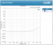
I do have the ability to measure THD+N vs frequency. See attached. Most of this measurement is the noise (+N) part of THD+N. The noise is higher in this measurement due to the wider measurement bandwidth (60 kHz) and noisier analyzer (the 192 kHz ADC in the APx525 is noisier than the 44.1 kHz ADC).
Anyway. Above a few kHz, you'll see the THD starts to creep out of the noise floor. The measurement was done at 100 W into 8 Ω.
Note that this was measured on the prototype, thus subject to change (likely for the better).
I agree with your observation of rising THD+N. If the THD+N rises above audible (0.01-0.1% depending on who you ask) within the audio band, I tend to perceive the sound as harsh.
Tom
I don't have the ability to measure THD vs frequency as the THD of the MOD686 is below the measurement noise floor and I only have one precision oscillator (Victor doesn't seem to make them anymore).
I do have the ability to measure THD+N vs frequency. See attached. Most of this measurement is the noise (+N) part of THD+N. The noise is higher in this measurement due to the wider measurement bandwidth (60 kHz) and noisier analyzer (the 192 kHz ADC in the APx525 is noisier than the 44.1 kHz ADC).
Anyway. Above a few kHz, you'll see the THD starts to creep out of the noise floor. The measurement was done at 100 W into 8 Ω.
Note that this was measured on the prototype, thus subject to change (likely for the better).
I agree with your observation of rising THD+N. If the THD+N rises above audible (0.01-0.1% depending on who you ask) within the audio band, I tend to perceive the sound as harsh.
Tom
Attachments
Last edited:
- Home
- Vendor's Bazaar
- Modulus-686: 380W (4Ω); 220W (8Ω) Balanced Composite Power Amp with extremely low THD