That's not to say that there aren't similar questions about 50/60 Hz 'linear' supplies.
True. Maybe the question should be phrased as "Is shielding more important when a SMPS is used versus a toroidal powered linear unregulated supply"?
Though I wonder if there is a chance for intermodulation of the two frequencies, either in the switcher itself or via radiation to the audio circuitry that would create a 10kHz 'birdie'?
Good question. I doubt the switcher would send any 10 kHz out. I would have picked it up in the FFTs if it did. All I see in the output noise spectrum of the amp is a bit of 60, 120, and 180 Hz hum. That's no surprise as the amp is sitting naked on my lab bench with absolutely no attempt of shielding and several flying leads in the signal path. Even then, I think the tallest hum component was measuring -120 dBV or so.
The obvious candidates for radiation would be the switch driver, transformer, and output diodes. That loop tends to have a fair amount of energy flowing through it. Thankfully, with SMD components the loop area can be made rather tiny, so radiation should be less of an issue.
Also, I wonder how much HF radiation, in general, one can anticipate between the SMTS and amp circuits in the close quarters of an amp chassis? (I.E., should the SMTSs be shielded from the audio circuitry?
In most DIY builds I can't imagine shielding being necessary. My lab setups are anything but clean and I often have the supply sitting a few inches from the amp under test. That said, a sheet of aluminum is pretty cheap...
Shielding is probably more appropriate in the cases where the amp board and SMPS board are sandwiched bottom-to-bottom as they are in the Benchmark ABH-2. Benchmark does add a shielding plate between the SMPS and the amp board, though that could have been done for marketing reasons as well.
Tom
Last edited:
Hi Tom
I got a question. You said earlier that the linear power supply drops the rail voltage under certain load conditions whereas the SMPS does not (or much less). Yet the 686 seems to perform (almost) identical in your measurements. Could you explain why? Are there no audible differences between the two power supply concepts?
Thx
SH
An unregulated supply will always droop under load. Any load. With a heavy load, such as a 4 Ω speaker, the droop will be several volts at the signal peaks if you drive the amp to near clipping.
A regulated supply (SMPS or not) will show only negligible droop. The SE-600-36 I've been using for testing have remote sensing, so I measure no droop at the power connector on the MOD686. There's probably a few mV of droop across the PCB traces when the amp is near clipping.
Recall: Output power: Pout = Vload_peak^2/(2*Rload)
Remember the MOD686 is a bridged amp, so (neglecting the Vce_sat drop across the LM3886 output devices) its maximum output swing is: Vload_peak = Supply*2.
Which of these builds do you think will produce the highest output power at clipping?
Let's do the math (assuming 4 Ω load):
If we include the saturation voltage of the LM3886 output stage, the math becomes:
Pout = ((Vsupply - Vce_sat)*2)^2/(2*Rload)
So assuming a 5 V drop across the output devices (Vce_sat = 5 V), the math becomes:
This is why you see the MOD686 clipping at a lower output power with the unregulated supply.
As long as you operate the MOD686 (or any of the other Modulus amps) away from clipping, they perform identically regardless of supply type.
I don't understand the second part of your question. "Why does the Modulus-686 provide good performance when it is operating with sufficient supply voltage?"
The Modulus-686 provides good performance with either supply type due to the error correction topology used.
Did this further your understanding a bit, or at least address your question?
Tom
A regulated supply (SMPS or not) will show only negligible droop. The SE-600-36 I've been using for testing have remote sensing, so I measure no droop at the power connector on the MOD686. There's probably a few mV of droop across the PCB traces when the amp is near clipping.
Recall: Output power: Pout = Vload_peak^2/(2*Rload)
Remember the MOD686 is a bridged amp, so (neglecting the Vce_sat drop across the LM3886 output devices) its maximum output swing is: Vload_peak = Supply*2.
Which of these builds do you think will produce the highest output power at clipping?
- MOD686, Build A, which is powered by an unregulated supply that produces ±36 V at idle and ±32 V at clipping.
- MO686 Build B, which is powered by an SMPS producing ±36 V at idle and ±35.995 V at clipping?
Let's do the math (assuming 4 Ω load):
- Build A: (32*2)^2/(2*4) = 512 W
- Build B: (35.995*2)^2/(2*4) = 648 W
If we include the saturation voltage of the LM3886 output stage, the math becomes:
Pout = ((Vsupply - Vce_sat)*2)^2/(2*Rload)
So assuming a 5 V drop across the output devices (Vce_sat = 5 V), the math becomes:
- Build A: ((32-5)*2)^2/(2*4) = 364 W
- Build B: ((35.995-5)*2)^2/(2*4) = 408 W
This is why you see the MOD686 clipping at a lower output power with the unregulated supply.
As long as you operate the MOD686 (or any of the other Modulus amps) away from clipping, they perform identically regardless of supply type.
I don't understand the second part of your question. "Why does the Modulus-686 provide good performance when it is operating with sufficient supply voltage?"
The Modulus-686 provides good performance with either supply type due to the error correction topology used.
Did this further your understanding a bit, or at least address your question?
Tom
Last edited:
I'm still puzzled by the second part of your question. Maybe I haven't done a good enough job at explaining the purpose of the composite topology. So let me try this:
A composite amplifier uses a precision amplifier to perform error correction on a less precise amplifier. In case of the Modulus-686, the LME49724 performs error correction on six LM3886es. This results in an amplifier that has the precision of the LME49724 and the power of six LM3886es. This is the central point of the composite architecture.
The composite architecture will correct for many types of error, such as distortion and supply-induced errors.
The error correction circuit in the MOD686 has its own regulated supply, so even if there is ripple on the supply to the board, the supply to the error correction circuit will have much, much, much less ripple due to the ripple reduction of the on-board regulators. On top of that, the error correction circuit (LME49724 and associated components) has its own supply rejection (PSRR of the LME49724 due to its design and architecture). The end result is that the error correction circuit will correct for any distortion and supply-induced error in the LM3886es, without introducing its own error, within the performance limitations of the LME49724.
Thus, as long as the power supply is within the range of ±20 V to ±36 V, the Modulus-686 will perform very well. The absolute maximum supply voltage is ±42 V. This limit is set by the LM3886es.
Due to the thermal limitations of the LM3886es there is no benefit of going beyond ±36 V. In fact, the LM3886es will overheat sooner with voltages above ±36 V, so the performance is more likely to degrade.
I hope this addresses the second part of your question.
Tom
As always .... wonderfully answered (both questions). Thanks a lot.
Regarding the second question. Before reading your above explanation I was under the erroneous impression that the rail voltage would drop with every quick and strong drum beat and could therefore lead to distortion. You explained above why this can not be, unless the amp is driven to clipping (which isn’t my regular listing level anyway ;-))
Regarding the second question. Before reading your above explanation I was under the erroneous impression that the rail voltage would drop with every quick and strong drum beat and could therefore lead to distortion. You explained above why this can not be, unless the amp is driven to clipping (which isn’t my regular listing level anyway ;-))
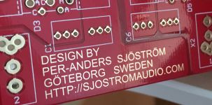
The gold surface is a bit "un-shiny" but I think this comes from the chemical process. Remember that you (normally) have nickel between the copper and the gold. And yes, it's true gold, 24 carat, but an extremely thin layer.
I have always ENIG on my boards just because it's looks nicer but as a side effect it's easier to solder.
BTW: tomchr, your pcb looks wonderful.
I have always ENIG on my boards just because it's looks nicer but as a side effect it's easier to solder.
BTW: tomchr, your pcb looks wonderful.
Last edited:
All exposed metal surfaces get this gold layer. Personally I write text in the solder mask if there is copper beneath, then I will get text in gold.Tom,
Regarding the gold platings, is it just on the pads or is it on the traces too? When referring to “gold” are you referring to true gold or the commonly used chemical gold?
Attachments
The little module I am using originally was at 110KHz. Seems like when the supplier looked at the data I sent them, they reduced the frequency. But I think it possibly may also depend on the quality of oscillation and the harmonics it generates. It is the harmonics that get into the EMI critical test range if I recall correctly. I can check the data.
I have a bunch of RS-15-5 that I had planned to use in a build. It turns out that when they see a load (15 mA), the change from idling at 130kHz to.... 8kHz.
At least that what I see on the scope.. 8-o
Warning!
//
Hmm, the measurements I was looking at were taken running 1KHz signal through the amp. Most of my trouble was in the conductive noise. Since this was a small module I really don’t see how they could switch the frequency with such a simple design. Normally I would expect higher frequency under load though. Lowering frequency does not seem to make sense. But if the current is too high, they do just shut down which is a nice feature, too much capacitance load would do that upon startup.
I have always ENIG on my boards just because it's looks nicer but as a side effect it's easier to solder.
My board manufacturer charges extra for the ENIG, so I haven't used it until now. For the hobbyist there isn't much difference between ENIG and the HASL solder coating I've been using until now. Maybe the ENIG is easier to solder to, I just haven't noticed.
My reason for going with ENIG is that my assembly house strongly recommends it. HASL is a solder coating. Solder oxidizes and is harder to clean. Gold is easy to clean because, as I mentioned a few posts back, nothing sticks to it. With gold plated boards, you can basically wipe off any dirt and run the boards through the assembly process.
BTW: tomchr, your pcb looks wonderful.
Thank you. I appreciate it.
All exposed metal surfaces get this gold layer. Personally I write text in the solder mask if there is copper beneath, then I will get text in gold.
That's a neat trick. OSH Park does the same thing. As a Husky (or at least UW graduate), I find it deeply ironic that OSH Park, located in Beaverton, OR, uses the University of Washington purple-and-gold colour scheme. Something tells me that was a conscious choice.
")
I have a bunch of RS-15-5 that I had planned to use in a build. It turns out that when they see a load (15 mA), the change from idling at 130kHz to.... 8kHz.
That sounds broken - or like a measurement error. If the switching frequency changes to 8 kHz, you should be able to hear them whine. Personally I suspect something else is going on.
Tom
I may be overly anal, but I've found one trick that I've adopted for all my through-hole assembly, and it should work on the surface of a naked solder-coated PCB. Oft times, my through-hole components have been sitting around a LONG time, and you often don't know how long parts from D-K or Mouser have been sitting around. Thus any solder plating has oxidized, as Tom stated, and does not readily whet in spite of good solder flux. The trick is to use a piece of Mr Clean 'Magic Eraser'. For leaded parts, squeeze a small chunk around the wire lead and slide/rotate it for a few seconds. The old oxide ends up on the eraser and the lead has a clean surface. The eraser is made of melamine foam and is a very fine abrasive, so little chance of doing anything bad to your lead (or PCB surface).
Hello Tom,
That is a really good news that you release an amp that can be an alternative to the nc400 !
I have a few questions if you don't mind
1- What residual noise can be expected with the 20dB gain setting?
2- Would there be a way to select the resistor with a switch so that the gain can be adjusted (something like 20dB/26dB/32dB) like on the Benchmark AHB2 ? Or would that degrade performance?
3- What is the idle power consumption?
4- Is the module noise-free on power on/off?
Thank you
That is a really good news that you release an amp that can be an alternative to the nc400 !
You're welcome.
1- What residual noise can be expected with the 20dB gain setting?
16 uV (A-weighted)
20 uV (unweighted)
Both: RMS, 20 Hz to 20 kHz.
2- Would there be a way to select the resistor with a switch so that the gain can be adjusted (something like 20dB/26dB/32dB) like on the Benchmark AHB2 ? Or would that degrade performance?
Bringing one of the most sensitive nodes in the circuit out to a switch is not my idea of a good time. Yes, it can be done. No, I don't recommend it.
A better way to accomplish the gain switching would be by relays or some other signal switching and then route the control signals to the switch, which I'm sure is what Benchmark does. I have no plans to change the board to include this feature, however.
3- What is the idle power consumption?
The prototype measures 365 mA at ±35 V, so 70*0.365 = 25.6 W. Most of this goes into the heat sink.
4- Is the module noise-free on power on/off?
Click and pop free, yes. It starts up and powers down cleanly both with single-ended (RCA) and differential (XLR) sources.
Tom

It is true that the Modulus-86 Rev. 1.0 -> 2.0 change resulted in a reduction in the turn-on pop (which was very low to start with). I forget the exact amount, but 2.5x sounds about right. The changes to the DC servo in Rev. 2.0 also reduced the settling time from a few minutes to about ten seconds.
Builders of the Modulus-86 who used RCA connections reported a larger pop, which I was able to verify. That pop was caused by the THAT1200 frontend of the Modulus-86. That is one of the main reasons I chose not to use the THAT1200 for the Modulus-686.
I have learned a lot since the Modulus-86. The Modulus-286 taught me quite a few things, both related to the circuitry and assembly. The HP-1 taught me some more things, in particular regarding compensation. I applied these lessons to the Modulus-686 to make a groundbreaking amp using the best circuit tricks and secret sauce I know of at this time.
Please do not assume that because X was true for Modulus-86 Rev. 1.0, X is also true for the Modulus-686. I will always make improvements and Modulus-86 Rev. 1.0 is coming up on its fourth anniversary now... I have learned a lot during that time. Also, if you compare the block diagram of the Modulus-86 with that of the Modulus-686, you will notice that the '686 is a completely different animal.
Lemme see if I can measure any turn-on pop on the Modulus-686. That way we have actual data to talk about. I'll see if I can squeeze that in this afternoon. Stay tuned.
Tom
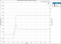
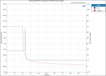
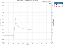
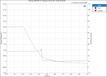
The promised measurements attached. The output voltage is in blue and indicated on the left vertical axis. The supply voltage is in red and plotted against the right vertical axis. The horizontal axis is time in seconds (10-second span). The supply was turned on/off at the 2-second mark. I did this by hand, so my reaction time is included here as well.
The startup and shutdown transients are a few mV for the Modulus-686 prototype. I think it's fair to say that the Modulus-686 starts up and powers down without any audible clicks or pops.
You get a little more of a turn-off transient with the lab supply as it discharges faster when it's turned off. The softer response of the Power-86 and Antek transformer is a bit gentler on the output transient.
Note that we're pretty far down in voltage here. We're talking a few millivolt of pop, max. The 800 uV output offset voltage provides a nice sense of scale.
I did measure the Modulus-86 Rev. 2.01 for comparison. The turn-on transient of the Modulus-686 is ~30x better than that of the Modulus-86 Rev. 2.0, which is ~2.5x better than Modulus-86 Rev. 1.0.
Told ya I was learnin' an' improvin'...
Tom
Attachments
-
 Modulus-686 PROTO_ Startup (HP 6643A Power Supply).PNG31.7 KB · Views: 585
 -
 Modulus-686 PROTO_ Shutdown (HP 6643A Power Supply).PNG31 KB · Views: 597
 -
 Modulus-686 PROTO_ Startup (Power-86 + Antek AN-5225).PNG32.5 KB · Views: 572
 -
 Modulus-686 PROTO_ Shutdown (Power-86 + Antek AN-5225).PNG30 KB · Views: 577
Last edited:
Thant is impressive, I am very tempted!
IIRC the mod64 v2 was said to have a on/off noise reduced by a 2.5 factor compared to v1, so about -8dB, which means it was still present and could potentially be heard with a very sensitive transducer (compression driver).
POS: don't hesitate. I used Ncore 400 monoblocks to drive the CDs on my M2s but then I made a pair of Parallel 86 monoblocks in bridged mode to drive the CDs. The P86s are even more transparent and neutral than the Ncores. The Ncores were relegated to the woofers. I've ordered the 686 PCBs and they will replace the Ncores on the woofers
PS: How is that new DSP crossover for the M2s coming along?
- Home
- Vendor's Bazaar
- Modulus-686: 380W (4Ω); 220W (8Ω) Balanced Composite Power Amp with extremely low THD