Hmmm, the Antek's output voltage under no-load conditions is 22.4VAC according to the manufacturer's datasheet. Multiplying that by sqrt(2) gives 31.7V peak. Multiplying that by a mains variation of 1.1X (ten percent, whereas USA spec is 7 percent) gives 34.8V peak. Adding in the unit to unit variation in primary-to-secondary turns ratio (zero variation) gives 34.8V peak. Subtracting two diode drops gives 33.8V peak across the capacitors. If this makes you uncomfortable when using 35V capacitors, by all means, shift to higher voltage units. The UFW1H103MRD is the same size capacitor, but now 50V rated. Capacitance drops from 15 thousand microfarads to 10 thousand microfarads. Total is now 20 thousand microfarads per rail, compared to the larger PCB on Power-86 which is 22 thousand microfarads per rail. Smaller pcb, smaller capacitance.
Measured secondary leakage inductance of the Antek AS-2222 is 1.6 microhenries; the inductance of a 1.5cm lead on the vertical mount snubber resistor is about 0.015 microhenries. Less than 1 percent. Nothing to be concerned about.
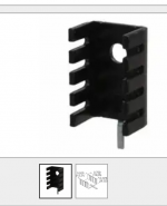
The diodes are mounted on Aavid 577102 heatsinks, same ones as on RingNot, picture below. The heatsink support leg is soldered to the PCB for additional support. The diodes themselves are in TO-220FP packages so you don't need shoulder washers or mica insulators for mounting. Just thermal compound, a bolt, a nut, and a drop of Loctite. The diodes' temperature rise above ambient, when delivering 220 watts to the electronic load for an hour, is 53 degrees C. Remember that the Antek transformer it only rated for 200 watts (200 VA); we're testing at 220 watts. Naturally, moving the diodes even further away from the capacitors would be even better, as Tom says. Don't make the board so small that it makes you nervous about overcooking the capacitors.
If you want to replace the eight resistors by eight jumpers, it will introduce extra inductance as Tom says. About 3 nanohenries in V+ and 3 nanohenries in V-. And then the power cables which connect the power supply board to the amplifier board, add a series inductance which is about 30X to 60X larger. That's why you install big honking bypass capacitors on the amplifier board itself: to minimize the supply impedance at the amplifier itself. That's why you choose low-ESR, low-ESL bypass capacitors for the amplifier board, and why you use several of them. To lessen the impact of the wiring harness inductance between the PSU and the amp.
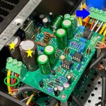
In the photo below, the PSU outputs are labeled with a blue arrow. The wiring harness enters the amplifier PCB at the green circle. The yellow stars indicate (some of!) the big honking bypass capacitors on the amplifier board itself. Notice the extremely low inductance (proportional to wire length) between bypass caps and the amplifier itself. Notice the much MUCH higher inductance between amp board and PSU. Compare that to the 3 nH introduced by jumpering out the 3W resistors.
_
Measured secondary leakage inductance of the Antek AS-2222 is 1.6 microhenries; the inductance of a 1.5cm lead on the vertical mount snubber resistor is about 0.015 microhenries. Less than 1 percent. Nothing to be concerned about.
The diodes are mounted on Aavid 577102 heatsinks, same ones as on RingNot, picture below. The heatsink support leg is soldered to the PCB for additional support. The diodes themselves are in TO-220FP packages so you don't need shoulder washers or mica insulators for mounting. Just thermal compound, a bolt, a nut, and a drop of Loctite. The diodes' temperature rise above ambient, when delivering 220 watts to the electronic load for an hour, is 53 degrees C. Remember that the Antek transformer it only rated for 200 watts (200 VA); we're testing at 220 watts. Naturally, moving the diodes even further away from the capacitors would be even better, as Tom says. Don't make the board so small that it makes you nervous about overcooking the capacitors.
If you want to replace the eight resistors by eight jumpers, it will introduce extra inductance as Tom says. About 3 nanohenries in V+ and 3 nanohenries in V-. And then the power cables which connect the power supply board to the amplifier board, add a series inductance which is about 30X to 60X larger. That's why you install big honking bypass capacitors on the amplifier board itself: to minimize the supply impedance at the amplifier itself. That's why you choose low-ESR, low-ESL bypass capacitors for the amplifier board, and why you use several of them. To lessen the impact of the wiring harness inductance between the PSU and the amp.
In the photo below, the PSU outputs are labeled with a blue arrow. The wiring harness enters the amplifier PCB at the green circle. The yellow stars indicate (some of!) the big honking bypass capacitors on the amplifier board itself. Notice the extremely low inductance (proportional to wire length) between bypass caps and the amplifier itself. Notice the much MUCH higher inductance between amp board and PSU. Compare that to the 3 nH introduced by jumpering out the 3W resistors.
_
Attachments
Notice the much MUCH higher inductance between amp board and PSU. Compare that to the 3 nH introduced by jumpering out the 3W resistors.
Valid point. But at least scrap the CRC filter by shorting out those Rs.
Tom
It does call attention to the futility of relentlessly minimizing supply inductance on the PSU board. "Planes and pours", blah blah. Careful attention to every detail got it down from 35 nanohenries to 8 nanohenries, congratulations. Now connect it in series with a 200 nanohenry wiring harness and see what a huge difference all that careful work has made to overall performance.
Find a way to tell your paying customers that time domain scope photos are a lie because AP cannot replicate their result. Also find a way to say that zero cost PCB stuffing options are foolishly misguided even though they are totally optional and even though they cost zero.
I remember when you used to say that the PCB stuffing options cost more than zero, and this stupid extra cost was a complete and total waste since the PCB options achieve absolutely and totally nothing.: link Good to see that you are able to adapt to the needs of the current marketplace today, especially towards the people whose previous actions suggest they are highly likely to send you money again.
I remember when you used to say that the PCB stuffing options cost more than zero, and this stupid extra cost was a complete and total waste since the PCB options achieve absolutely and totally nothing.: link Good to see that you are able to adapt to the needs of the current marketplace today, especially towards the people whose previous actions suggest they are highly likely to send you money again.
Mark Johnson, your approach seems to be what at my place of work we call 'pigeon management'. Swoop in from nowhere, crap over everything, and then swoop out. What sort of axe do you have to grind, or are you just trying to prove technical machisma by dropping in and nit picking? It seems you only show up when you are trying to push your bridge-rectifier-filter-cap-RCR-filter design.
Not wanting to get into a discussion that diverts from the purpose of this thread, which is to support people building with Tom's amplifier module, so this is the last thing I'll say. Your main interest appears to be to discourage people from buying Tom's power supply module in favor of building with your similar module which you have generously 'open sourced'. You also appear to consider your CRC snubber and test gizmo as documented in your Linear Audio article and thread elsewhere on this forum to be superior to any other snubber approach for 50/60 Hz transformer-based supply. You also appear to consider it essential to good audio performance of the final project (amp, preamp, DAC, whatever). Yet I can point out others that either (a) don't seem to consider it a big deal and/or (b) make good technical arguments for other approaches. Namely:
-- Neither Self nor Cordell devote a lot of ink to this topic in their encyclopedic books on amplifier design. I suspect they consider it a minor or insignificant issue.
-- I can remember at least one Linear Audio article that had a fairly extensive analysis and concluded that one only needed a 'C' snubber, and also concluded that for the vast majority of cases one could get a close-to-optimum solution with 1000pF and no additional analysis or measurement required.
-- I've seen many other discussions on the topic, but those have all been in the context of high-frequency switching supplies where the magnitude of ringing induced by rectifier switching becomes a serious issue.
I have yet to see anything other than solid engineering from Tom and his offerings. Any minor quibbles I've had, I've discussed with him off-line rather than (potentially) compromising his business by appearing to cast dispersion in public.
Yes, someone could build your open-source supply board or design their own for less money than Tom's, assuming that they choose to invest their time in such a project and have the technical knowledge and PCB design capabilities to do so. DIYers on this forum come in all levels of experience -- there's no admission requirement of being a degreed Electrical Engineer. Tom appears interested in providing the building blocks that enable even a 'newbie' with basic mechanical / kit-assembly skills to build a state-of-the-art amplifier. I believe he gives good value for what he charges and can only continue to do so if that results sufficient ROI to support himself.
Very well said. Thank you.
I stand by the claims I make regarding my products. They are rooted in science and engineering. I measure the performance of my circuits with calibrated state-of-the-art equipment. I'm not forcing anyone to buy. If you believe you can get better value elsewhere, or would rather cook your own, you're certainly welcome to do that.
Tom
Yet I can point out others that either (a) don't seem to consider it a big deal and/or (b) make good technical arguments for other approaches. Namely:
-- Neither Self nor Cordell devote a lot of ink to this topic in their encyclopedic books on amplifier design. I suspect they consider it a minor or insignificant issue.
You can add Rod Elliot to the list. He has a recent article against this practice. The article seems to specifically call out Mark’s approach.
Thanks for the link to the Rod Elliott article! I'll call attention to it over in the snubber optimization thread, and there's a good chance it will stimulate some follow on discussions.
My reading of Elliott's article is that he agrees with tomchar on many points:
I myself think it's safer (more conservative) to completely eliminate ringing altogether, by installing a snubber. Then we don't care whether the supply behaves as it "should". No ringing means no possibility of any effect upon the DC output. And the change which completely eliminates ringing, is easy and inexpensive. Why not put it in, and sleep better.
My reading of Elliott's article is that he agrees with tomchar on many points:
- The transformer secondary RLC resonant circuit does actually ring (Figure 8)
- Adding a snubber reduces the amplitude and frequency of ringing
- You can adjust the snubber component values (he uses decade substitution boxes) to make ringing completely disappear (Figure 13)
- But none of this matters at all, because ringing on the secondary has no effect upon the output of the linear power supply, the DC
I myself think it's safer (more conservative) to completely eliminate ringing altogether, by installing a snubber. Then we don't care whether the supply behaves as it "should". No ringing means no possibility of any effect upon the DC output. And the change which completely eliminates ringing, is easy and inexpensive. Why not put it in, and sleep better.
If the snubber has an effect on the output DC voltage, its effect should be measured, or at the very least simulated in a circuit simulator.
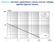
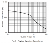
To further the understanding of this topic, it is worth noting that the ringing occurs when the diodes turn off - i.e. after they have "disconnected" the power transformer secondary from the output of the power supply. Thus, in order for any ringing to make it to the output of the power supply, it would have to couple through the capacitance of the reverse biased diodes. This capacitance forms a capacitive divider with the supply reservoir cap.
I looked up the reverse capacitance of a large-die rectifier diode. See below. You'll notice the reverse capacitance is sizeable - 35-120 pF depending on the reverse voltage, for the reverse voltages relevant to the Power-86 and Power-686. However, even at the highest capacitance shown in the graph, the capacitive divider formed by the reverse capacitance and the 22000 uF bulk cap in the Power-86 (44000 uF in the Power-686) results in 165 dB of attenuation of anything that occurs on the input side of the reverse biased diodes. At 100 V reverse bias, the attenuation increases to 185 dB.
Are you seriously telling the world that the ringing is so severe that 165-185 dB attenuation plus the PSRR of the audio amplifier isn't enough to suppress it well below the noise floor?
You can always claim that something "might" affect something else. Or emphasize the "should" in someone's claim that something should not affect something else. Or change "will not" to "should not". Snake oil salesmen have been doing that for decades. Speaker cable stands, anyone? The triboelectric force resulting from micro-vibration between your nonconductive flooring and speaker cables may repel the electrons as they bounce from micro-diode to micro-diode within the cable. "Just because you can't measure it, doesn't mean it isn't true". Clearly, you need to buy my proprietary **PATENT PENDING** Oregonian Myrtlewood Speaker Cable Stands. That's the only solution.
I firmly believe that extraordinary claims need to be backed up by extraordinary evidence. That's why I measure the performance of my circuits and provide them for everyone to see.
The part of Rod Elliott's article that I took particular note of is found in the conclusion:
Tom
To further the understanding of this topic, it is worth noting that the ringing occurs when the diodes turn off - i.e. after they have "disconnected" the power transformer secondary from the output of the power supply. Thus, in order for any ringing to make it to the output of the power supply, it would have to couple through the capacitance of the reverse biased diodes. This capacitance forms a capacitive divider with the supply reservoir cap.
I looked up the reverse capacitance of a large-die rectifier diode. See below. You'll notice the reverse capacitance is sizeable - 35-120 pF depending on the reverse voltage, for the reverse voltages relevant to the Power-86 and Power-686. However, even at the highest capacitance shown in the graph, the capacitive divider formed by the reverse capacitance and the 22000 uF bulk cap in the Power-86 (44000 uF in the Power-686) results in 165 dB of attenuation of anything that occurs on the input side of the reverse biased diodes. At 100 V reverse bias, the attenuation increases to 185 dB.
Are you seriously telling the world that the ringing is so severe that 165-185 dB attenuation plus the PSRR of the audio amplifier isn't enough to suppress it well below the noise floor?
You can always claim that something "might" affect something else. Or emphasize the "should" in someone's claim that something should not affect something else. Or change "will not" to "should not". Snake oil salesmen have been doing that for decades. Speaker cable stands, anyone? The triboelectric force resulting from micro-vibration between your nonconductive flooring and speaker cables may repel the electrons as they bounce from micro-diode to micro-diode within the cable. "Just because you can't measure it, doesn't mean it isn't true". Clearly, you need to buy my proprietary **PATENT PENDING** Oregonian Myrtlewood Speaker Cable Stands. That's the only solution.
I firmly believe that extraordinary claims need to be backed up by extraordinary evidence. That's why I measure the performance of my circuits and provide them for everyone to see.
The part of Rod Elliott's article that I took particular note of is found in the conclusion:
Emphasis mine.Building a test circuit that first creates the illusion of a problem, then claims to provide a 'simple fix' is obviously of little use to man or beast. The article that prompted all of this goes into great detail, and has lots of maths in the appendix that describe the phenomenon of ringing. However, the writer appears to have missed that the 'injection' capacitor was the root cause of ringing in the first place. Once that's removed from the equation there may not be a problem to fix! If there really is a problem, it's far better to analyse it in the final circuit with a representative load.
Tom
Attachments
Last edited:
")
Hi Tom, here's another high power diode, rated for 30 amperes continuous current, TO-220 package, made by Vishay. Capacitance at switchoff (bias = 0) is a little more than 2500 picofarads.
I suggest that nobody WANTS ringing, not even Rod Elliott. He says in part 2 that eliminating ringing might be a good thing, if for no other reason than it improves the conducted emissions portion of Radio Frequency Interference testing. He also says,
I (MJ) suggest that eliminating the unwanted ringing is possible, in fact easy, so easy that Rod Elliott himself managed to do it (see scope photos in Part 2). I suggest that the cost of eliminating ringing is tiny (2 small caps and 1 resistor per secondary). I myself conclude that it's a worthwhile use of my money, to pay for these low cost components and to install them in my board. Others might come to the opposite conclusion of course. Give people the option and let them make their own decision.
Sometimes I compare transformer secondary ringing to an unsightly wart on a person's face. It may or may not be harmless. But it certainly IS unsightly. Why not remove it, especially when the cost to make it completely disappear is very low?
_
I suggest that nobody WANTS ringing, not even Rod Elliott. He says in part 2 that eliminating ringing might be a good thing, if for no other reason than it improves the conducted emissions portion of Radio Frequency Interference testing. He also says,
This is an article where, in an attempt to prove that something was completely unnecessary, I discovered that this may not be the case.
I (MJ) suggest that eliminating the unwanted ringing is possible, in fact easy, so easy that Rod Elliott himself managed to do it (see scope photos in Part 2). I suggest that the cost of eliminating ringing is tiny (2 small caps and 1 resistor per secondary). I myself conclude that it's a worthwhile use of my money, to pay for these low cost components and to install them in my board. Others might come to the opposite conclusion of course. Give people the option and let them make their own decision.
Sometimes I compare transformer secondary ringing to an unsightly wart on a person's face. It may or may not be harmless. But it certainly IS unsightly. Why not remove it, especially when the cost to make it completely disappear is very low?
_
Attachments
Mark I use your quasimodo every time I build any psu, its really helpful, your shitting in tom's backyard really isnt. Its not a great look, really. If people want toms solution they'll use them, we aren't sheep, we do read other threads.
Simon, mod86p, ringnot and quasimodo owner.
Simon, mod86p, ringnot and quasimodo owner.
On a more serious note, here are data.
My starting point was the Power-686. So rectifier, reservoir caps, options for CRC snubber, etc. on a well-designed circuit board.
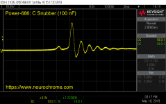
I started with no snubber. I then added my default C snubber (C = 100 nF).
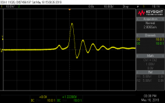
I decided to give Mark the benefit of the doubt and try his CRC snubber. Mark was kind enough to provide a link to a thread that's dedicated to listings of CRC values for various transformers. My Antek AN-5225 was unfortunately not on the list, but the AS-4218 was. The CRC values for this transformer (150 nF, 11.5 Ω, 10 nF) are similar to other Antek toroidal transformers in the thread, so I doubt there's a lot of variation. I used 150 nF, 10 Ω, 10 nF, which should result in a slightly over-damped system (i.e. a system with minimal or no overshoot).
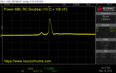
Finally, I tried Rod Elliott's RC snubber. Following Rod's lead, I used 10 Ω, 100 nF.
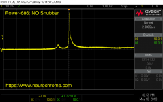
I measured the secondary voltage using the same method as Rod used (1 kΩ + 10 nF RC highpass filter connected across the secondary) using a 70 MHz oscilloscope. You can see the results below.
Results:
For the circuit with NO snubber, I found no ringing. The amplitude of the inductive flyback is significant, though. This finding is congruent with Rod Elliott's findings.
My simple C snubber reduced the flyback amplitude, but also created a bit of ringing. The frequency of the ringing is quite low, hence, unlikely to couple into sensitive circuitry.
Mark's CRC snubber creates the same ringing as my simple C snubber. The frequency of the ringing is a bit lower as Mark recommends C = 150 nF versus my C = 100 nF. The CRC snubber appears as effective or ineffective as the simple C snubber. It provides fundamentally the same result using three times the number of parts.
Rod Elliott's RC snubber is where it's at. It does a fine job of lowering the flyback amplitude and settles with only a tiny bit of overshoot.
From this point forward, I will recommend that you use either NO snubber or the simple RC snubber (R = 10 Ω, C = 100 nF). The effect of the addition of snubbers is not measurable on the output of the power supply, thus, will not impact the performance of the connected circuitry. As Rod Elliott points out, there may be cases where snubbers are needed; for example in cases where the equipment needs to pass an EMC test for conducted EMI.
Tom
My starting point was the Power-686. So rectifier, reservoir caps, options for CRC snubber, etc. on a well-designed circuit board.
I started with no snubber. I then added my default C snubber (C = 100 nF).
I decided to give Mark the benefit of the doubt and try his CRC snubber. Mark was kind enough to provide a link to a thread that's dedicated to listings of CRC values for various transformers. My Antek AN-5225 was unfortunately not on the list, but the AS-4218 was. The CRC values for this transformer (150 nF, 11.5 Ω, 10 nF) are similar to other Antek toroidal transformers in the thread, so I doubt there's a lot of variation. I used 150 nF, 10 Ω, 10 nF, which should result in a slightly over-damped system (i.e. a system with minimal or no overshoot).
Finally, I tried Rod Elliott's RC snubber. Following Rod's lead, I used 10 Ω, 100 nF.
I measured the secondary voltage using the same method as Rod used (1 kΩ + 10 nF RC highpass filter connected across the secondary) using a 70 MHz oscilloscope. You can see the results below.
Results:
For the circuit with NO snubber, I found no ringing. The amplitude of the inductive flyback is significant, though. This finding is congruent with Rod Elliott's findings.
My simple C snubber reduced the flyback amplitude, but also created a bit of ringing. The frequency of the ringing is quite low, hence, unlikely to couple into sensitive circuitry.
Mark's CRC snubber creates the same ringing as my simple C snubber. The frequency of the ringing is a bit lower as Mark recommends C = 150 nF versus my C = 100 nF. The CRC snubber appears as effective or ineffective as the simple C snubber. It provides fundamentally the same result using three times the number of parts.
Rod Elliott's RC snubber is where it's at. It does a fine job of lowering the flyback amplitude and settles with only a tiny bit of overshoot.
From this point forward, I will recommend that you use either NO snubber or the simple RC snubber (R = 10 Ω, C = 100 nF). The effect of the addition of snubbers is not measurable on the output of the power supply, thus, will not impact the performance of the connected circuitry. As Rod Elliott points out, there may be cases where snubbers are needed; for example in cases where the equipment needs to pass an EMC test for conducted EMI.
Tom
Attachments
Last edited:
Mark I use your quasimodo every time I build any psu, its really helpful, your shitting in tom's backyard really isnt. Its not a great look, really. If people want toms solution they'll use them, we aren't sheep, we do read other threads.
Well said.
Tom
Simon, I have praised Tom's decision to put the C+RC snubber components (PCB footprints) on his new revision of the power supply PCBs. If I remember correctly, he's done this on the 200 VA board and also on the 600 VA board.
A praiseworthy decision and, in my opinion, a wise one. Well done!
A praiseworthy decision and, in my opinion, a wise one. Well done!
- Home
- Vendor's Bazaar
- Modulus-686: 380W (4Ω); 220W (8Ω) Balanced Composite Power Amp with extremely low THD