Builds like yours make me sleep a lot better at night.
Tom
I must admit, your modules and their design makes it a whole lot easier to put everything together.
BTW, earlier today I was cheating a little while the amp is burning in its 48 hours, and I started to listen a few tracks while the equipment was connected using RCA (SE). Then out of curiosity, decided to switch to XLR (balanced) using all balanced source (same DAC). It makes a good difference with this amplifier on the micro details. I guess because we get full differential up to the end of the chain? The only other fully differential amplifier I have is the AMB B24 but I will not be comparing them. I don't have speaker protection on the B24 and decided to put it aside when my new ATS-4 speakers were completed. I will eventually add speaker protection though.
All the best!
Do
See page 9 of the ISS documentation. R6 controls the intensity of the LED in the ON position. R7 the intensity in STDBY. If you don't want any standby indication, just pluck R7. You can also insert a diode (1N4148 or 1N4007 for example) in series with the LED.
Some momentary switches have polarity markings on the LED connections, but really feature bidirectional LEDs. I find that highly annoying, especially as this "feature" isn't covered in the data sheet. Bad manufacturer! Bad!")
Tom
Some momentary switches have polarity markings on the LED connections, but really feature bidirectional LEDs. I find that highly annoying, especially as this "feature" isn't covered in the data sheet. Bad manufacturer! Bad!
Tom
Tom,
I know you like to use the precrimped leads from Molex (which are end of lifed). Have you ever tried to crimp the connectors to the wire? It may be easy using Molex's crimping tool, but it is a bit pricy. All I have is a standard crimping tool/wire stripper unit. Also looks like the nothing else seems to fit the 5.70 mm pitch of the mega-fit on the Mod686 boards.
I know you like to use the precrimped leads from Molex (which are end of lifed). Have you ever tried to crimp the connectors to the wire? It may be easy using Molex's crimping tool, but it is a bit pricy. All I have is a standard crimping tool/wire stripper unit. Also looks like the nothing else seems to fit the 5.70 mm pitch of the mega-fit on the Mod686 boards.
I think Molex had a model update on the connectors and terminals. It took me a bit to find the replacement for the 16 AWG 300 mm pre-crimped wire.
Mouser P/N: 538-79758-2038
Molex P/N: 79758-2038
Mouser has 2800+ in stock...
Now about your question: I know someone who contributed to this thread used the crimp terminals. I think if you crimp to the best of your ability and give them a dab of solder, they'll probably work just fine. I recommend using the pre-crimped leads, though.
Tom
There are many safe operating points. As I'm sure you're aware, safe does not necessarily mean good performance.
The maximum guaranteed output current of the MOD686 is 21 A (7 A per LM3886; 3 LM3886es per amp half, bridged), so you risk bumping into the current limit above 21*2 = 42 V swing. This requires some ±25-26 V supply voltage. If you keep the LM3886es cool and get typical silicon, you can get up to 33 A -> 66 V swing -> ±36 V supply voltage.
At ±30 V, you dissipate more than 240 W in the LM3886es with a 2 Ω load and music signal (14 dB CF). I'd consider that the thermal limit.
If you want something that's safe and provides good performance, I'd recommend ±24-26 V based on math. ±24 V will provide over 400 W into 2 Ω with the MOD686. You'll need a 300 VA power transformer per channel for music signal reproduction; 1 kVA/channel for sine wave.
I tested the MOD686 at 1 Ω with ±36 V supply once by accident. It delivered several hundred watt before my power supply shut down due to over-current. I don't have a power supply beefy enough to test the MOD686 with 1-2 Ω load. I wouldn't design for that operating point due to the thermal dissipation. At ±36 V, 2 Ω load, the MOD686 dissipates 350 W in the heat sink when delivering music signal at clipping levels. 530 W dissipated at the worst case operating point. This requires liquid cooling!
I generally don't recommend pushing past 35-40 W dissipated in each LM3886 as the SPiKe protection starts to engage, which degrades performance. This is especially true when the chip gets hot. Keep the heat sink temperature below 60-65 ºC.
Tom
The maximum guaranteed output current of the MOD686 is 21 A (7 A per LM3886; 3 LM3886es per amp half, bridged), so you risk bumping into the current limit above 21*2 = 42 V swing. This requires some ±25-26 V supply voltage. If you keep the LM3886es cool and get typical silicon, you can get up to 33 A -> 66 V swing -> ±36 V supply voltage.
At ±30 V, you dissipate more than 240 W in the LM3886es with a 2 Ω load and music signal (14 dB CF). I'd consider that the thermal limit.
If you want something that's safe and provides good performance, I'd recommend ±24-26 V based on math. ±24 V will provide over 400 W into 2 Ω with the MOD686. You'll need a 300 VA power transformer per channel for music signal reproduction; 1 kVA/channel for sine wave.
I tested the MOD686 at 1 Ω with ±36 V supply once by accident. It delivered several hundred watt before my power supply shut down due to over-current.
I don't have a power supply beefy enough to test the MOD686 with 1-2 Ω load. I wouldn't design for that operating point due to the thermal dissipation. At ±36 V, 2 Ω load, the MOD686 dissipates 350 W in the heat sink when delivering music signal at clipping levels. 530 W dissipated at the worst case operating point. This requires liquid cooling! I generally don't recommend pushing past 35-40 W dissipated in each LM3886 as the SPiKe protection starts to engage, which degrades performance. This is especially true when the chip gets hot. Keep the heat sink temperature below 60-65 ºC.
Tom
Last edited:
Thanks for the quick response, just ordered 2 of the MOD686. Plan to run them around +- 25v for the woofers in active 2 way, and using the MOD286-kit I ordered last week for the mid/high horns.
There are many safe operating points. As I'm sure you're aware, safe does not necessarily mean good performance.
The maximum guaranteed output current of the MOD686 is 21 A (7 A per LM3886; 3 LM3886es per amp half, bridged), so you risk bumping into the current limit above 21*2 = 42 V swing. This requires some ±25-26 V supply voltage. If you keep the LM3886es cool and get typical silicon, you can get up to 33 A -> 66 V swing -> ±36 V supply voltage.
At ±30 V, you dissipate more than 240 W in the LM3886es with a 2 Ω load and music signal (14 dB CF). I'd consider that the thermal limit.
If you want something that's safe and provides good performance, I'd recommend ±24-26 V based on math. ±24 V will provide over 400 W into 2 Ω with the MOD686. You'll need a 300 VA power transformer per channel for music signal reproduction; 1 kVA/channel for sine wave.
I tested the MOD686 at 1 Ω with ±36 V supply once by accident. It delivered several hundred watt before my power supply shut down due to over-current.
I generally don't recommend pushing past 35-40 W dissipated in each LM3886 as the SPiKe protection starts to engage, which degrades performance. This is especially true when the chip gets hot. Keep the heat sink temperature below 60-65 ºC.
Tom
Last edited:
Thanks for the quick response, just ordered 2 of the MOD686. Plan to run them around +- 25v for the woofers in active 2 way, and using the MOD286-kit I ordered last week for the mid/high horns.
Fantastic. That'll be a good operating point. I dropped your boards off yesterday and you should see the tracking start to update by tonight.
Tom
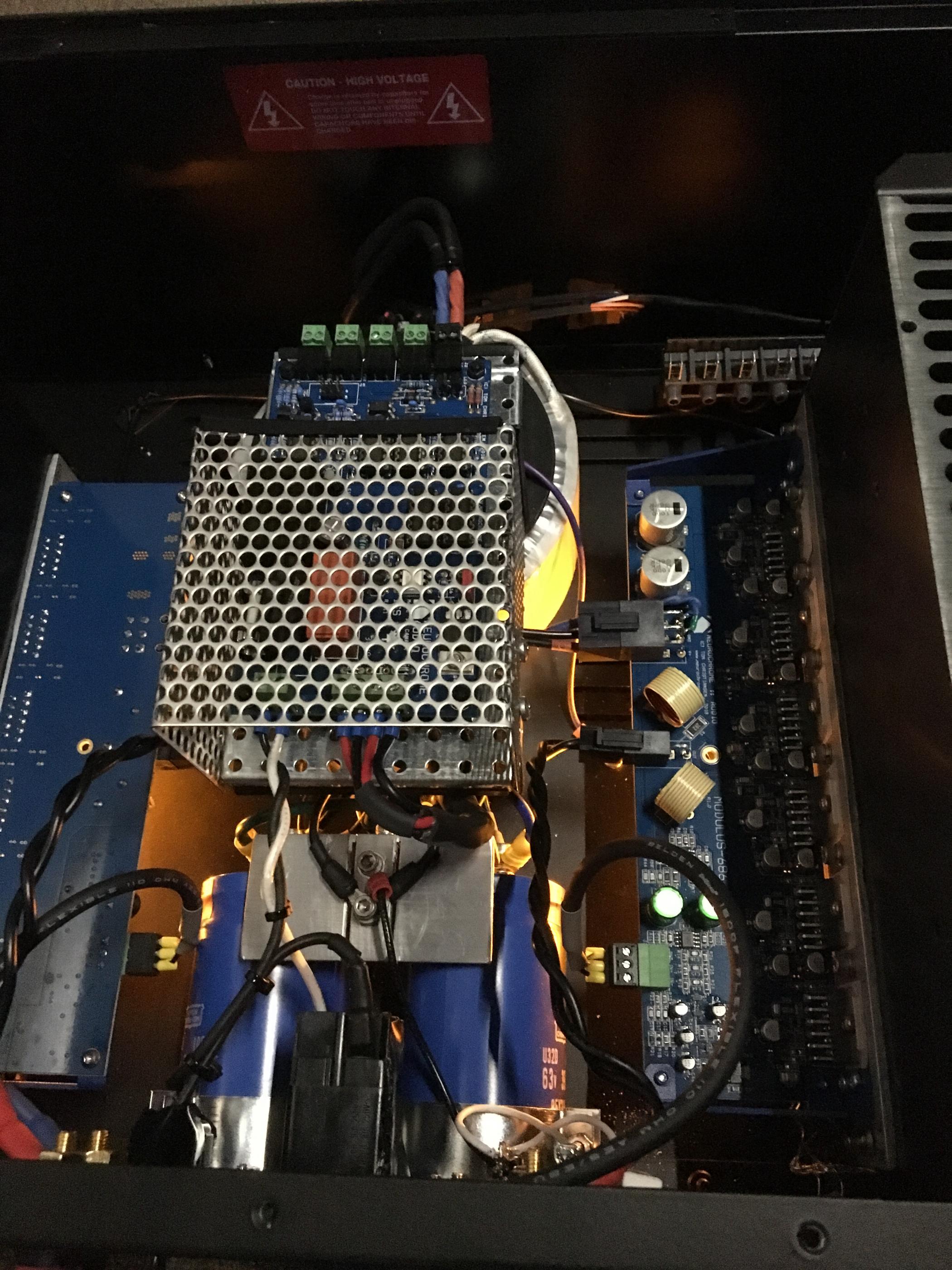
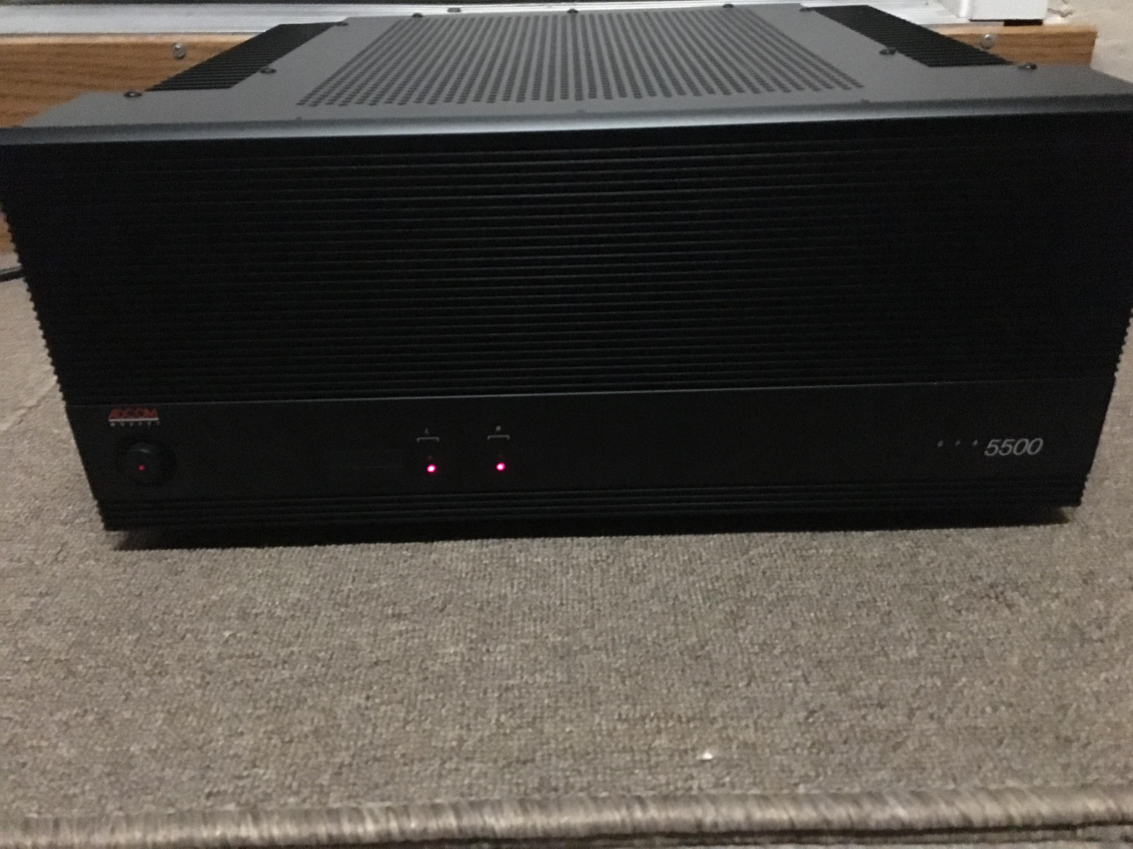
A nice Modulus-686 build turned up in the Chipamp Photo Gallery thread: Chip Amp Photo Gallery
This builder repurposed an old Adcom chassis with heat sinks. His build turned out really nice, so I thought I'd crosspost here.
A few teaser images (there are more linked to above).
Tom
This builder repurposed an old Adcom chassis with heat sinks. His build turned out really nice, so I thought I'd crosspost here.
A few teaser images (there are more linked to above).
Tom
Tom,
I have 2 - 2x22V 200VA Antek transformers sitting around. Could they be paralleled to supply one of my amps with a Mod 686 and 2-Mod 86 modules? I would get a 400VA transformer for the other amp. Seems to be enough room to stack the two 200VA transformers in a 3U height enclosure.
I have 2 - 2x22V 200VA Antek transformers sitting around. Could they be paralleled to supply one of my amps with a Mod 686 and 2-Mod 86 modules? I would get a 400VA transformer for the other amp. Seems to be enough room to stack the two 200VA transformers in a 3U height enclosure.
Parallelling transformers is not a good idea. Due to part-to-part variation, they'll produce slightly different output voltages and, unless fitted with ballast resistors, one will end up providing a lion's share of the current.
A better idea would be to power the Modulus-686 with one 2x22 VAC transformer and the two Modulus-86 with the other. 200 VA is plenty for the MOD86 and just enough for music reproduction for a single Modulus-686 channel at the resulting ±28-30 V supply voltage.
Tom
A better idea would be to power the Modulus-686 with one 2x22 VAC transformer and the two Modulus-86 with the other. 200 VA is plenty for the MOD86 and just enough for music reproduction for a single Modulus-686 channel at the resulting ±28-30 V supply voltage.
Tom
I thought of that, but I would need to have 2 Power-86’s in the enclosure, one for the Mod-86s and one for the Mod-686. Tight fit in the mini-dissapante enclosure.
Oy. Yeah... That's a bit of a squeeze. Sadly, you will need two Power-86es if you want to use two transformers.
I could still use one ISS for both?
Yep.
Tom
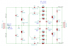
If you don't mind dropping down to thirty thousand microfarads per rail (2 x Mouser p/n 647-UFW1V153MRD), and if you also don't mind laying out a new PCB, then you can get something smaller than the Power-86. Here's a little design study that I did last year, which dropped the PCB dimensions down to 68mm x 98mm board size. The mounting holes align with the 1 cm grid drilled in the floor panels of diyAudio store / Modushop / HiFi2000 chassis: 6 cm X 9 cm. The Nichicon UFW goldsleeve caps I used are pretty tall, check the Mouser datasheet, maybe they're too tall for your application. Some people would of course replace the 0R39 3W resistors with jumper wires 
Do it yourself; consider laying out your own board to meet your own needs. Mine, for example, includes CRC snubbers and indicator LEDs. You may not want those.
_
Do it yourself; consider laying out your own board to meet your own needs. Mine, for example, includes CRC snubbers and indicator LEDs. You may not want those.
_
Attachments
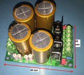
If you cook your own supply, I definitely recommend going with 50-63 V rated caps. The 35 V types in Mark's design don't quite cut it - especially once mains variation and part-to-part variation in the power transformer are taken into account.
I'm one of those who would scrap the CRC filtering. The added R does hardly anything for filtering (the cut-off frequency with the values shown above is 109 Hz), but causes a lot of supply bounce on the signal peaks. Sure, you can add wire links, but that adds inductance. I'd rather have a low-inductance plane connecting the caps.
Further, I would lay down the snubber resistors to minimize their lead inductance. If you're going through the trouble of adding CRC snubbers, you may as well make the snubber work well. I'd scoot the caps away from the heat sinks, so you don't cook the caps. Even a few mm of room goes a long way.
I can't quite tell from the picture, but it looks like the heat sinks are just dangling from the diodes. I would prefer that they were soldered or otherwise mechanically tied to the board to prevent their solder joints from failing over time.
Tom
- Home
- Vendor's Bazaar
- Modulus-686: 380W (4Ω); 220W (8Ω) Balanced Composite Power Amp with extremely low THD