Studley, it would be best to have electrical continuity between all the pieces of metal in a chassis. One could sand the contact area between panels and between panels and heat sink. Jumpers aren't a bad idea if you can't make good electrical contact with the physical contact. Usually screws or rivets between the components should be able to provide contact.
I presume I should defeat this by sanding a small area and putting a jumper across to the back panel?
Yeah. It's best to have all metal bits - especially those that can be accessed by the user - connected together and grounded.
Congratulations..
Thank you.
Tom
I am toying with the idea of having my circuit boards manufactured in Canada. The prices of the domestic manufacturing have come down quite a bit. While domestic manufacturing does cost a bit more than the East Asian manufacturing, there might be some value in having the manufacturing done locally. The question is mostly whether this adds value for those who buy and build the boards.
I have put together a little survey with 19 questions. 15 of them are simple multiple choice questions. Four are open-ended. Would you please help me out by taking this survey: Neurochrome Attitudes Survey.
The survey is hosted by Google, so you'll need a Google/gmail account to sign in. Your responses will be anonymous.
Thanks in advance for your help.
Tom
Last edited:
Studley, it would be best to have electrical continuity between all the pieces of metal in a chassis. One could sand the contact area between panels and between panels and heat sink. Jumpers aren't a bad idea if you can't make good electrical contact with the physical contact. Usually screws or rivets between the components should be able to provide contact.
Thank you and to Tom, I thought as much as I guess if you put enough volts through it the heatsink surface will become conductive.
I'm thinking the nonlinear resistance of the bulb is confusing the heck out of either the inrush limiter or the power factor correction circuit in the Mean Well supply that you're using.
I'd remove the bulb tester.
Tom
Thanks Tom. I'll check all the connections (again) and then try it without the bulb tester.
I am toying with the idea of having my circuit boards manufactured in Canada. The prices of the domestic manufacturing have come down quite a bit. While domestic manufacturing does cost a bit more than the East Asian manufacturing, there might be some value in having the manufacturing done locally. The question is mostly whether this adds value for those who buy and build the boards.
I have put together a little survey with 19 questions. 15 of them are simple multiple choice questions. Four are open-ended. Would you please help me out by taking this survey: Neurochrome Attitudes Survey.
The survey is hosted by Google, so you'll need a Google/gmail account to sign in. Your responses will be anonymous.
Thanks in advance for your help.
Tom
Hi Tom
I don’t have a google account nor do I intend to get one. If you send me the survey by PM I will be happy to fill it out though.
BR
SH
Thank you and to Tom, I thought as much as I guess if you put enough volts through it the heatsink surface will become conductive.
Anything can be made conductive. Just up the voltage.
")
Also, you're likely to have a thin spot in the anodized coating of the heat sinks or chassis somewhere. Maybe the parts got dinged or rubbed against something at one point. It doesn't take much to expose a little metal, especially along the edges. So you go to pick up your amp and get zapped due to an electrical fault somewhere. That would suck. I'd much rather have the fuse blow when the fault happen. At least that'll prompt you to do some fault finding.
Tom
Taking them to Munich then
They're probably better than a lot of the amps I'll be hearing . . .
They're probably better than a lot of the amps I'll be hearing . . .
yep!
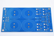
The Power-686 is taking shape.
I decided to spin the soft start circuit off as a separate board as it made the supply board really unwieldy. Something tells me it'll be easier to sell the boards if they actually fit in any available chassis...
The Power-686 measures 3.30 x 5.70 inches. The assembled height will be just shy of 60 mm, including the pins that protrude through the board.
Tom
Attachments
The Power-686 is taking shape.
I decided to spin the soft start circuit off as a separate board as it made the supply board really unwieldy. Something tells me it'll be easier to sell the boards if they actually fit in any available chassis...
The Power-686 measures 3.30 x 5.70 inches. The assembled height will be just shy of 60 mm, including the pins that protrude through the board.
Tom
Can you use indifferently transformers with two separate secondary or with one secondary with central wiring?
It’s a bo
Thanks! Gimme a couple of hours. I plan to get it on my website tonight. $59 for the bare board.
When do you estimate will the softstart board be ready?
Early July. Maybe sooner if the prototyping goes well.
Can you use indifferently transformers with two separate secondary or with one secondary with central wiring?
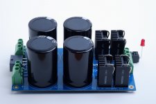
Absolutely! You can use a transformer with two secondary windings and transformers with one centre-tapped secondary with the Power-686.
The assembly is shaping up.
Tom
Attachments
The Power-686 is now available for purchase on my website: Buy your Power-686
You can find the list of features and other details here: Power-686
Tom
You can find the list of features and other details here: Power-686
Tom
Last edited:
Power supply
What kind of power supply circuit did you use, is there a pcb at all for this? Or dis you manually wire the caps and diodes together?
Looks impressive!
What kind of power supply circuit did you use, is there a pcb at all for this? Or dis you manually wire the caps and diodes together?
Looks impressive!
My version of this amazing amplifier. I thought id share my experience of building this amplifier.
I went for a 3U Modushop case, 300VA 22V Airlink transformers, and 47000uF Kemet PEH200 capacitors. The soft start and speaker terminals came from Ebay, capacitors from Elektro Dump, most of the rest came from Farnell.
Anybody that has experience of using basic tools such as, Soldering iron, tape measure, pistol drill, files, screwdrivers Ext is capable of building this amp.
It was a bit of a squeeze fitting everything in due to the large capacitors I chose to use, but managed to just fit everything in. I mounted one board upside-down to keep the wiring symmetrical and the input away from the transformers. Mounting the Lm3886's was a bit messy as I used far to much thermal grease with the mica insulators. I soldered in the Lm3886'S by just to pins at first, marked out the holes and soldered the rest of the pins when the chips were fully mounted on the heat sinks. Most of the power supply wiring was done with some old speaker wire that I had left over. Everything else was fairly straight forward marking out drilling and filing.
After double checking the speaker terminals and Lm3886's were not shorting to ground, the polarity of the capacitors and rectifiers, I powered up, much to my relief everything was fine with only .5mv at the output and sweet sounds emanating from my speakers.
- Home
- Vendor's Bazaar
- Modulus-686: 380W (4Ω); 220W (8Ω) Balanced Composite Power Amp with extremely low THD