Hi folks
I'm building a DAC and am on the output stage part of the process.
The DAC chips are I out so there will be an I/V conversion stage, then a LC filter, then a zero gain buffer stage.
I decided to use the B1 design for the buffer, with a few modifications, which I need some guidance with.
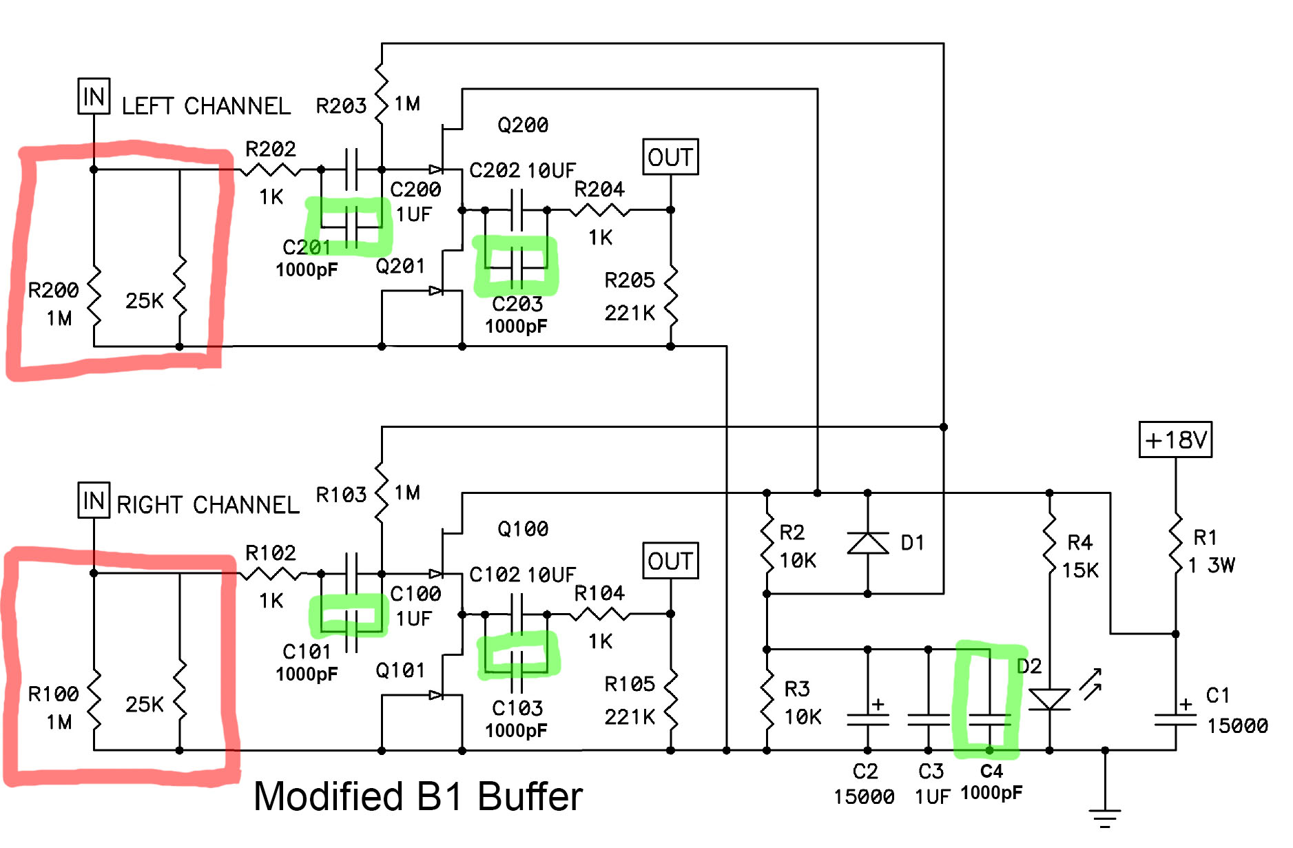
I don't need the multiple inputs nor the potentiometers, so I've removed those (area marked in red) and have substituted a 25k resistor for the pots.
What I'm wondering, is the 25k resistor and the 1M one remaining, actually necessary, can I remove those too?
I've added five 1000pF polypropylene caps to bypass the 1uf and 10uf caps, which are polyester types in my build. (marked in green)
Any other modifications people suggest given the particular application I'm using this buffer for?
I'm building a DAC and am on the output stage part of the process.
The DAC chips are I out so there will be an I/V conversion stage, then a LC filter, then a zero gain buffer stage.
I decided to use the B1 design for the buffer, with a few modifications, which I need some guidance with.
I don't need the multiple inputs nor the potentiometers, so I've removed those (area marked in red) and have substituted a 25k resistor for the pots.
What I'm wondering, is the 25k resistor and the 1M one remaining, actually necessary, can I remove those too?
I've added five 1000pF polypropylene caps to bypass the 1uf and 10uf caps, which are polyester types in my build. (marked in green)
Any other modifications people suggest given the particular application I'm using this buffer for?
Attachments
What's the R2 version? I haven't come across that before.
Schematic attached above.
Yes, I studied that, cheers. What is the functional difference to the normal B1? What are D+ and D-?
B1 R2 is DC coupled, so it doesn't need any input/output capacitors, but it requires symmetric power supply D+/D-. You can only use it if your DAC IV doesn't have any DC on the output.
Simple answer to OP is:
- You keep 25k resistor unless the previous stage can assume its function. 1M can be removed.
- adding 1000p will neither hurt nor improve performance
Thankyou, very useful. I happened to have a bag of 100pcs of the 1000pF so I figured why not.
Do you think I should have used a higher value than 1000pF to bypass the Russian PIO Caps I'm using for the 1uF and 10uF on my buffer? Or is it just not worthwhile to use any bypass cap at all?
B1 R2 is DC coupled, so it doesn't need any input/output capacitors, but it requires symmetric power supply D+/D-. You can only use it if your DAC IV doesn't have any DC on the output.
That's interesting, I happen to have a Toroidal transformer with dual 18v outputs that I could use to power it.
Is there a SQ increase in going for the R2's DC coupled route over the original B1?
Do you think I should have used a higher value than 1000pF to bypass the Russian PIO Caps I'm using for the 1uF and 10uF on my buffer? Or is it just not worthwhile to use any bypass cap at all?
Playing with capacitor types and bypassing is a black art. You don't know the anser in advance. So you first listen awhile then you make a change and so on in multiple iterations. But from experience, don't expect big differences. In my DAC I have electrolytic cap in the signal path (not bypassed). Perhaps polypropilen of the same capacity (100uF !) would sound better but, you know...
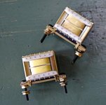
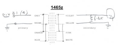
I was planning to use B1 R2 for the output buffer for my DAC. I/V conversion is done by Sowter 1465 transformers.
@ Qwertyl
What is Your I/V schematic with xformer ?
Something similar to Dave work from IntactAudio ?
:: View topic - Zen I/V with transformers.
Intact Audio
Attachments
I'll try to work my way through that 200+ page thread, but is there actually a consensus as to whether the SEN IV outperforms the ZEN IV? I'd be using it as the IV stage for a pair of PCM1798s running in dual mono mode.
Zen I/V contains first order LPF. How much filtering and type of filtering is important decision in DAC design. Use only polypropilen or polystyrene capaciors for this purpose (or same grade types). For more than first order filtering you need more active stages between i/v and output B1.
What is Your I/V schematic with xformer ?
At the moment it is simply 1465 transformer connected directly to DAC out with 6k8 resistor on the secondary.
Attachments
- Status
- This old topic is closed. If you want to reopen this topic, contact a moderator using the "Report Post" button.
- Home
- Amplifiers
- Pass Labs
- Modify B1 Buffer for DAC output stage