wow nice speaker you have there ! thanks for showing me, i get more understand about them now.
Well, i was thinking te first mod would be easier, but less clearer signal (as you said earlier)
I was thinking to remove the tape section for light weight and less power consume, as I seen, the cable to tape only a few adapter, so i think i can just unplug it, is it ?
As in for CD input, the whole adapter consist of 6 terminal :
- CD-H
- CD.GND
- L.CH
- R.CH
- P.GND
- P.VDD
So my idea is to disconnect the whole adapter from the CD board, which permanently exclude CD player from the Radio Player.(Save Electric Cost)Then I just connect the audio cable to "L.CH","R.CH","CD.GND" individually. Thats is my plan now !
But 1 more problem arise now, other than mainboard connected to the CD board(the connect which we disconnect just now), there is also another connection to control board. (CNP802) Would my plan affects the sound of the audio when i use input ?
I have one more idea, which is i unplug the connection to the headphone female adapter, then rewire it into the circuit we mention earlier, which is the input.
So conclusion is making the output headphone female adapter into a AUx input. (from outer source)
I don't quite get the circuitry of the headphone, mind help me research on that ? thank you.")
Example :
- How to rewire the line to speaker directly after remove the headphone female adapter from the output circuit.
So conclusion is making the output headphone female adapter into a AUx input. (from outer source)
I don't quite get the circuitry of the headphone, mind help me research on that ? thank you.
Example :
- How to rewire the line to speaker directly after remove the headphone female adapter from the output circuit.
Ok ,let's put it straight !!!
You want to amplify and hear a loud sound ,so you don't need headphones (same do I ) ;moreover , the headphone jack adds two more contacts in the signal path . How does it work ? The connector has also a double 2 way switch that is normally closed ,and when you insert the plug ,they're open (no sound from the speakers ) and routed to the TRS internally ,attenuated by some resistors (to match headphones impedance) . Usually this don't affect the sound,at least at these power levels ( I think this arrangement would melt if used with more than 20-30 W ). Infact ,in powerful compact stereos ,the internal switch of the HP jack commands the output relays .
Now...speaking of standards : TRS (3,5 mm - mini jack)is made for mini-portable devices ,also for light headphones ; same female connectors with an internal switch can be found in audio inputs-outputs of a computer (with 5 channels ): the computer knows which jack is used and routes the signal because inserting the plug it commands a switch , which controls trough the logic some 'analogue' (don't confuse with mechanical) switch ,like the one you have for selecting inputs . Did I tell you RCAs are far better ?
Basically , what you are going to do is fairly easy and straight : isolate the amplifier circuit and use it for your purposes . So you need to check the PCB traces and CUT what you don't need ( in excess ...),you'll end with a 10x10 cm board with two chips, some capacitors ,resistors . And obviously the PSU (don't mind of the other secondary).Wiring from PSU to amp board should be as short as possible .In battery operated systems ,the mains plug contains a switch , either ,which allows current from batteries to flow . In other words ,such things are well engineered and almost stupid-proof ,but in the end they are like toys ,compared to real hi-fi gear .
Now ,you have the connector that goes to the speakers ,and you have to build an input connector (you can also cut the plug from a stereo chord and use it for experimenting ,soldering the R-L-GND wires to the R-L inputs and ground ).Using the HP jack may be a real pain ....you'll have to de-solder it ,short the contacts where they are supposed to be closed ,then re-use that jack for input..
I find it a lot easier using RCAs ,I made a lot of cables from TRS to RCA..when I cannot find them ready made .
Well...... i'm quite weak on circuit tracing, because i don't know which stuffs i need and don't need CLEARLY in my mind. (such as when the circuit goes to volume control IC, do i need to continue tracing ? etc...) So we also need to preserve the headphones and speaker output connection ?
Would be very good if you can help me in this tracing job, but its far too troublesome to have to do it for me.
But i think you could 'direct' me about how to trace what i need in this project.
So in your words, i should wire RCA instead of TRS ? if so, how should i accomplish ? (RCA stereo uses 2 connector, instead of TRS use 1 connector) So what would be the wiring will be if so ?
And suddenly I remembered..... does this player consist of snubber ?(if not wrong, is to prevent sudden voltage drop/increase, which cause 'boom')
And by the mean of HP Jack, how is its looks like ? But its not big deal, since we are not going to use it(troublesome).
One more additional issue, but its not a big problem. Its about the speaker wiring, the speaker are connected to player with wire by clipping style (just a stripped end wire clipped into the terminal) which is quite weak and often spoil the wire easily.
I was thinking of crimping with a conductive metal piece end as connector to the slipper, is it a good idea ?
Some more thing to ask:
There is 3 connection to external just below the main plug in the power supply page/board.
Which marks as arrows of 1 black 2 white, which labeled as 'B+' line also.
About the plug, it is only 2 for AC '+' & '-', is it necessary to make a ground line for safety/quality purpose ?
There is 3 connection to external just below the main plug in the power supply page/board.
Which marks as arrows of 1 black 2 white, which labeled as 'B+' line also.
About the plug, it is only 2 for AC '+' & '-', is it necessary to make a ground line for safety/quality purpose ?
Hi ! It makes me loose my sleep ...
Sooooo ...what's going on ? haven't you fired it up yet ?
The most important things for us are pictured on the top -left of page 32 & 38 ,which are the amplifier and the PSU schematics. Since it is also battery operated ,the way it 'senses' when putting them on service ,is when you extract
the mains plug :it contains a switch that closes the contacts between one pole of the battery and the circuit .The pole is B+ (Battery positive ) ,as you may see ...after the rectifier (the big one ,with capacitors across each diode) the current first goes to that switch ,which is the one contained in the 'AC-in' outlet: if there is no plug inserted ,the battery is allowed to work . Just remove the wires from battery .
Much difficult is to solder the 'hot' and 'ground' connections to the input of the amplifier : that is pin number 12 (see the arrow ?!? ). For safety reasons (for not allowing DC to be amplified ) it should be better to keep the 1 uF electrolytic capacitor (C116-216) ;also ,you should pull out by desoldering them , Q 101-201 transistors (which mute the input): So the (+) of C116-216 are our inputs ,cut the traces before them ,and solder a wire on that buttonhole ,carefully . So we may end in having the left and the right wires . And the ground ?? Wherever , near the inputs .
Ok ,now you should be done . Since the apparatus is a double insulation safety class , it does not need any ground connection ....well ,from the moment you open it ...
And... should I explain how to connect an RCA ???? Or how to twist the stranded wires of the speaker cables to insert them into the clips ?
Edit : It's not working !!!! Don't panic ,it's just the Standby pins of the amp (pin 8) that don't receive any reference voltage . Just connect a 10 K Ohm resistor from pin 8 and B+ (resistors are marked with 3 colored bands : you need black-brown-orange...or is it brown-black-orange ????ha ha haaa ) or any value between 8000 and 15 K Ohm.
Last edited:
Sorry to trouble you quite alot (near to losing sleep state)
Do you mean Top Right, instead of top-left ? So i just cut out the batteries line (abandon it)?
**I guess is following the way of the manual, because 2nd method need to do alot of rewiring ? But I'm not too sure about the ground/sleeve of input(RCA) should wire to black line of PSU, or amplifier...**
I mean if i use the crimping style(encase a copper plate) instead just putting the wires into the 'clipper', would it disturb or downgrade the audio quality ? (because of different conductor material in the way)
So in conclusion, after isolating the powerboard (disconnect the battery connection and others), and isolating the amplifier along with the headphone & speaker(cut just before C116, C216, Q101, Q201, pin 4 & 8), then how should we connect ? (pin 4 & 8, PSU and others)
I think the pin 4 would connect to the top(black dot) to the PSU, but i have no idea connect pin 8 to what, even i had to put in a resistor(which you told).
And a bold black wire from Amplifier to page 37 through -<2>-, should we cut slightly outside region of Amplifier, then connect it to second dot(White dot) to PSU ? (i think it serves as grounding)
Then no need to connect other things to the PSU at the 3 other wiring ?
And about the output of the speaker volume, since i don't have internal volume control as in our modification, the volume control is from outer source and it will as if the magnitude of volume radio player has been turned to maximum volume in the original condition ? (example : the input of radio is about 5dB, then amplified to 10dB through maximum volume of original condition. Then after we modification, if the input is 5dB, it is set to amplify to 10dB)
Do you mean Top Right, instead of top-left ? So i just cut out the batteries line (abandon it)?
Do you mean we cut just before C116, C216, Q101, Q201, pin 8 & 4 ? then de-solder the Q101 and Q201 transistor and leave the other wiring as it is ? So thats the way to isolate the amplifier ?also ,you should pull out by desoldering them , Q 101-201 transistors (which mute the input): So the (+) of C116-216 are our inputs ,cut the traces before them ,and solder a wire on that buttonhole ,carefully . So we may end in having the left and the right wires . And the ground ?? Wherever , near the inputs .
About the RCA, i need 2 RCA connection for left and right, isn't it ? I mean i connect the each RCA's tip/inner(signal) to pin 12 to both amplifier(like on the manual), or pin 11 & 12 individually ? and RCA's sleeve(ground) to pin 13 to both amplifier, or pin 10 & 13 individually ? (these connection I meant is all before those capacitor/resistor, not directly to the pin)should I explain how to connect an RCA ???? Or how to twist the stranded wires of the speaker cables to insert them into the clips ?
**I guess is following the way of the manual, because 2nd method need to do alot of rewiring ? But I'm not too sure about the ground/sleeve of input(RCA) should wire to black line of PSU, or amplifier...**
I mean if i use the crimping style(encase a copper plate) instead just putting the wires into the 'clipper', would it disturb or downgrade the audio quality ? (because of different conductor material in the way)
So in conclusion, after isolating the powerboard (disconnect the battery connection and others), and isolating the amplifier along with the headphone & speaker(cut just before C116, C216, Q101, Q201, pin 4 & 8), then how should we connect ? (pin 4 & 8, PSU and others)
I think the pin 4 would connect to the top(black dot) to the PSU, but i have no idea connect pin 8 to what, even i had to put in a resistor(which you told).
And a bold black wire from Amplifier to page 37 through -<2>-, should we cut slightly outside region of Amplifier, then connect it to second dot(White dot) to PSU ? (i think it serves as grounding)
Then no need to connect other things to the PSU at the 3 other wiring ?
And about the output of the speaker volume, since i don't have internal volume control as in our modification, the volume control is from outer source and it will as if the magnitude of volume radio player has been turned to maximum volume in the original condition ? (example : the input of radio is about 5dB, then amplified to 10dB through maximum volume of original condition. Then after we modification, if the input is 5dB, it is set to amplify to 10dB)
There is also a capacitor just outside of the powerboard/PSU, which is C348(4700 16V), do we need to preserve it ?
There is also another worrying issue may occur. You have said most power usage are based on 5V 6.2V, I also agree with it, but it seems the power supply written is about 9V if directly connected, but i think it is ok since the amplifier have wide operating range, or what do you think about it ?
Since it don't have the control panel include in it, do we need to make a on/off switch for it ?
There is also a backup board beside battery board, below PSU, does it important, or we can ignore it ?
Last edited:
Don't matter ....I was dreaming of my 12" in 120 liter boxes I'm just finishing I dream they were just attached without any filter and they sounded fabulous Today I should glue the front baffle ...and try 'em 
OK : pin 14 and 15 are Power Ground (they are tied together )and pin 7 is also ground...for line level signals you should consider this pin as Gnd .
I guess that on the PCB ,the C348 (4700 uF -16 VL )is located close to pin 4 (+ Vcc ,same as +B...)and pins 14-15 because there is where is needed .
Just bring two wires from the output of the diode bridge to the buttonholes of that capacitor ,respecting the polarity . Now the power is supplied .
For connecting the line level signal ,you can also desolder one leg (+)of C116-216 and lift it ,and solder the wire there .Usually shielded cable is used ,
but it is not peremptory. The shield is the ground ( O V ) of course.
Two wires (black -negative ; red -positive ...or whatever) bring power to the amp . 4 wires exit from it (note :the amp works in BTL so there is no Gnd reference at the Black connector for Spkr output ) . Three wires ( or 2+2 )which are Right & Left channels plus Ground brings the input signal .
I expect some sound exiting from this device after these mods .
I dream they were just attached without any filter and they sounded fabulous Today I should glue the front baffle ...and try 'em OK : pin 14 and 15 are Power Ground (they are tied together )and pin 7 is also ground...for line level signals you should consider this pin as Gnd .
I guess that on the PCB ,the C348 (4700 uF -16 VL )is located close to pin 4 (+ Vcc ,same as +B...)and pins 14-15 because there is where is needed .
Just bring two wires from the output of the diode bridge to the buttonholes of that capacitor ,respecting the polarity . Now the power is supplied .
For connecting the line level signal ,you can also desolder one leg (+)of C116-216 and lift it ,and solder the wire there .Usually shielded cable is used ,
but it is not peremptory. The shield is the ground ( O V ) of course.
Two wires (black -negative ; red -positive ...or whatever) bring power to the amp . 4 wires exit from it (note :the amp works in BTL so there is no Gnd reference at the Black connector for Spkr output ) . Three wires ( or 2+2 )which are Right & Left channels plus Ground brings the input signal .
I expect some sound exiting from this device after these mods .
Let me see them ! X.x I think it will be excellent !
I don't know about shielded cable, could you show me some picture or links ?
So we are really ignoring(not connect to anything) the other 3 wiring of PSU to mainboard, and the backup board ?
So we should preserve the C348, is it ? As it is in original(C348) ? Then connect the as the manual, is it ? (excluding parts we don't need)I guess that on the PCB ,the C348 (4700 uF -16 VL )is located close to pin 4 (+ Vcc ,same as +B...)and pins 14-15 because there is where is needed .
Just bring two wires from the output of the diode bridge to the buttonholes of that capacitor ,respecting the polarity . Now the power is supplied .
So you mean that the external input signal of L&R should be soldered to the leg of those 2 capacitor respectively ?For connecting the line level signal ,you can also desolder one leg (+)of C116-216 and lift it ,and solder the wire there .Usually shielded cable is used ,
but it is not peremptory. The shield is the ground ( O V ) of course.
I don't know about shielded cable, could you show me some picture or links ?
So we are really ignoring(not connect to anything) the other 3 wiring of PSU to mainboard, and the backup board ?
ahhh..... that short and quick answer was kind of ambiguous, and for which statement ? (elaborate would make the statement non-ambiguous)
If i were to apply this plan, I would transfer those things to another boxes (most of the time), which greatly reduce the spaces occupied. Therefore the transformer may be near, or should i don't do that ?(shift to make a external transformer thingy)
If i were to apply this plan, I would transfer those things to another boxes (most of the time), which greatly reduce the spaces occupied. Therefore the transformer may be near, or should i don't do that ?(shift to make a external transformer thingy)
Ha ha the dream box...almost a nightmare ! My car-accessories seller had just finished bitumen+fluffy foils for cabinet dampening , so if I want to finish I have to manage and adapt by myself ...as usual...it's DIY !! I was thinking also of steel reinforcements ...but I think I'm going with ...wood !?!?
Woofer 12"-midrange 6"-tweeter 1" ....sensibility will be around 93 dB/W/m...
I have just put together a PC to make measurements and simulations ...but that's a real PITA !
the dream box...almost a nightmare ! My car-accessories seller had just finished bitumen+fluffy foils for cabinet dampening , so if I want to finish I have to manage and adapt by myself ...as usual...it's DIY !! I was thinking also of steel reinforcements ...but I think I'm going with ...wood !?!?Woofer 12"-midrange 6"-tweeter 1" ....sensibility will be around 93 dB/W/m...
I have just put together a PC to make measurements and simulations ...but that's a real PITA !
 Thread moved to "Everything Else"
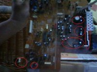
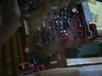
I have manage to trace out the location and encircle it, just to have opinion on you guys :
- the components are a bit too far in a board, therefore i want to make it closer (to a smaller size, but same board).
The main problem is that the connection need to connect the headphone to the front, therefore distant those 2 section.
My idea is to remove headphone side section (which consist of L101/201/301, C134/234, R119/219)
Is it possible to completely bypass that section ? (component I concern is the capacitor & Resistor)
Thanks in advance.
Attachments
Last edited:
Now i noticed some problem with the radio, but not fatal.
The white noise(static) is quite loud if ANY electricity is conduct in the input (ANY)
Any way to determine what is the problem ? I use it on computer, and heard the white noise when there is no media playing.
I also tested with earphone with maximum volume, but no white noise is heard in ear phone, but if i put the earphone through the radio, it is obvious.
So it must within the area from input to BEFORE speaker. But i couldn't pinpoint the problem.
Note : when the input is not connected to anything (exposed to air), there is absolutely no sound produced, so probably the problem is within the input area/device ?
- Status
- This old topic is closed. If you want to reopen this topic, contact a moderator using the "Report Post" button.
- Home
- General Interest
- Everything Else
- modification to my old radio