I have an old radio (well... maybe 10 years or so) which the CD player is faulty, and tape feature(which most of us didn't use nowadays). 
It doesn't have any line-in for me to input any other audio hardware which i can make use of the radio (as a speaker).
I kind of like it, so I decided to modify it make it useful.
My idea was to rectify the CD input into a line-in port, which most modern music players have. I will interested to hear others idea and opinion.
I have the manual of schematic circuit drawing of that particular radio player called PHC-ZW770L.
But I myself couldn't fully have the idea where should I edit it, as I only have little knowledge about audio. These are the following problem i'm facing:
- As commonly known, a stereo adapter have 3 wiring, which is ground, Left & Right. I'm thinking of connect these 3 wiring of another line in cable to take over CD's wiring.
In the circuit board, i only found/know it have a L&R-channel input, but i didn't found any words match of grounding purposes. ( the part consists of wiring such as "R.CH", "L.CH", "CD.5V(CD-H)", "CD.GND", "P.GND", "P.VDD(6.2V)"
- Is it possible to just disconnect the wiring for CD's and Tape' to save electricity(as in didn't use at all), or we need to edit a little bit to do so ? (like changing resistors as so on).
Colour by numbers :
R.CH.......Right channel
"L.CH"......Left
"CD.5V(CD-H)....CD High -Logic status
"CD.GND" Ground
"P.GND" Power Ground and "P.VDD(6.2V)".....Power supply...whether or not "D" stand for Digital ,surely by cutting those connections ,the CD section won't receive any power . I guess the input selection is made via an electronic switch ,which may send itself an 'high' logic level to CD-H pin .
The same function is accomplished via mechanical switches in an usual (self-activating at tape function push ) tape section,which usually feed the motors ,either .
A tester to check voltages and logic levels may be useful .
R.CH.......Right channel
"L.CH"......Left
"CD.5V(CD-H)....CD High -Logic status
"CD.GND" Ground
"P.GND" Power Ground and "P.VDD(6.2V)".....Power supply...whether or not "D" stand for Digital
,surely by cutting those connections ,the CD section won't receive any power . I guess the input selection is made via an electronic switch ,which may send itself an 'high' logic level to CD-H pin .The same function is accomplished via mechanical switches in an usual (self-activating at tape function push ) tape section,which usually feed the motors ,either .
A tester to check voltages and logic levels may be useful .
Colour by numbers :
R.CH.......Right channel
"L.CH"......Left
"CD.5V(CD-H)....CD High -Logic status
"CD.GND" Ground
"P.GND" Power Ground and "P.VDD(6.2V)".....Power supply...whether or not "D" stand for Digital
The same function is accomplished via mechanical switches in an usual (self-activating at tape function push ) tape section,which usually feed the motors ,either .
A tester to check voltages and logic levels may be useful .
Hm...... don't quite understand fully, but I will ask for clarify, such as :
- CD High ? Logic status ? (understand it somehow related to logic gate, but could you give a example that what it may be, and how it works)
- CD.GND and PWR GND, what is the different ? (to which connection).
- I checked wikipedia, and VDD stands for +terminal
- What I meant is thatt if i cut off the power for CD player, will it make the systems unbalance ? (such as radio itself take too much of power or so on)
So, in your opinion, i'm make a additional stereo input line(TRS system), which has 3 terminal:
Tip Terminal - Left Terminal - L.CH
Ring Terminal - Right Terminal - R.CH
Sleeve Terminal - Ground Terminal - CD.GND ??(not sure)
Should that be the connection ? or the sleeve terminal connect to P.GND/CD-H ?
I had to say thanks first of all for your reply, it gives me a lot of information.Colour by numbers :
R.CH.......Right channel
"L.CH"......Left
"CD.5V(CD-H)....CD High -Logic status
"CD.GND" Ground
"P.GND" Power Ground and "P.VDD(6.2V)".....Power supply...whether or not "D" stand for Digital
The same function is accomplished via mechanical switches in an usual (self-activating at tape function push ) tape section,which usually feed the motors ,either .
A tester to check voltages and logic levels may be useful .
There is something i'm not very clear about what you said :
- CD High ? Logic Status ? (well... i know it is related to logic gate, but can you explain by giving some example what it works for)
- CD.GND / P.GND, what is it connected ?
- VDD stands for +terminal
- If the CD player power was cut out, will the radio player itself would get damaged some imbalance power ?
I wanted to replace the CD input to external input (input line), was thinking to mount a 3.5mm trs female connector, so what would be correct combination ?
There is also control panel for CD player, would it affect my input sounds ? (such as the left&Right channel is not detected, so no sounds release from CD mode (which the input replace by external source)Tip terminal - L.CH
Ring Terminal - R.CH
Sleeve Terminal - CD.GND (very uncertain)
No change to "P.GND", "P.VDD", "CD.5V(CD-H)",
Would this be the correct connection ?
MMhhhh..From my point of view , better install and use classic RCA cinch ,they're 'heavy duty' compared to the 3,5 mm stereo jacks .
Cutting the Vdd and Gnd (also)lines would fully disconnect the CD section ...at the very end you could physically cut the part
Usually the signal (L and R) exits the CD section with two (1---4 uF ) capacitors, so you'll have to check if the following stage is AC or DC coupled...but at 99 % also the source you'll use will be DC coupled with its own output capacitor
Digital ground and main ground (and positive ) are usually kept separate ,to prevent noises go trough the supply lines . Don't know if CD -H brings also the 5 V for the ICs..Would be useful to know ( you may use it to activate a relay which switches a device ...).
Would be also very keen of you if you take a look at the inside of the amp , and tell which model or kind is the (integrated) amp I like to keep in touch ( read : read the datasheets ) with the beast that controls my mind
Cutting the Vdd and Gnd (also)lines would fully disconnect the CD section ...at the very end you could physically cut the part
Usually the signal (L and R) exits the CD section with two (1---4 uF ) capacitors, so you'll have to check if the following stage is AC or DC coupled...but at 99 % also the source you'll use will be DC coupled with its own output capacitor
Digital ground and main ground (and positive ) are usually kept separate ,to prevent noises go trough the supply lines . Don't know if CD -H brings also the 5 V for the ICs..Would be useful to know ( you may use it to activate a relay which switches a device ...).
Would be also very keen of you if you take a look at the inside of the amp , and tell which model or kind is the (integrated) amp
I like to keep in touch ( read : read the datasheets ) with the beast that controls my mind LOL.... Beast within ? X.x and sorry for accidentally double-posted (wrong clicked)
Well.... naturally RCA is better in terms of heavy duty, but most of the time, my input is from computer or mp players, so i make it TRS is going to make my life easier. But i was thinking, maybe i should make it RCA then convert it to TRS, so its better ? (or is it possible to make 2 parallel input line of RCA and TRS ? which make it quite universal)
As mention in he 2nd paragraph in your post, the GND means for P.GND ? (well... sometimes i'm quite confused with those different term, so better to spell the complete name )
In the 3rd paragraph, you mention about the L&R Channel, but i don't quite get it, but is it ok to just directly connect the input from computer or other source directly to the "L.CH","R.CH" ? (which is Tip&Ring Terminal in the term of TRS connector)
In the 4th paragraph, about the digital ground and main ground, could you specific what is the abbreviation used ?(like P.GND ?)
Well.... I like to fulfill your wish for look at the Amp, but too bad i'm not good at these thingy (this thingy is kinda old system, very complicated, unlike computer internal connection, seems mixed up)
But I can take a photo of it and let you see which is it, then we can know the features and constructions.
I also have a schematic diagram of the radio, but is it legal to post it here for you ? or any forums rules against that ?
But I can take a photo of it and let you see which is it, then we can know the features and constructions.
I also have a schematic diagram of the radio, but is it legal to post it here for you ? or any forums rules against that ?
I found this manual online, i guess it will helps alot
http://www.promelec.ru/UPLOAD/xml/scheme/PHC-ZW770L.pdf
The part I mention is KH306, on page 4(bottom right corner), should be the vital piece for my project
http://www.promelec.ru/UPLOAD/xml/scheme/PHC-ZW770L.pdf
The part I mention is KH306, on page 4(bottom right corner), should be the vital piece for my project
Could not resist to say : now it's time to dismantle the speaker !!
Funny thing ...I had a boombox very similar but older without cdp...same kind of amplifiers ,same VC equalizer ,but REAL switch(...a switch ! )and also Aux-CD input . Funnier thing is that the speakers were so good that now they are employed in my main speakers (helped by two woofers each).
So...good luck ! Now you have everything you need to do the changes
well.... its true, they are very good in term of quality (better then my new speaker brought in PC Fair...)
You mean by dismantle the speaker, what should i connect ? *confused*
The switch you mean is a old classical ? But yours got input, i don't have any (maybe after modification)
WHAT SHOULD I CHANGE ? thats the main problem i have, haha.....
If i assume i use a TRS type of connection,
the tip should connect to "L.CH",
the ring should connect to "R.CH"
and the sleeve connect to "what" ?
What should be connected and what it is use for ? I would assume it is connected to "CD.GND" ? Since "P.GND" and "P.VDD" would most of the time supply power line for CD Player, "CD-H" would most of the time related only to logic gate, which is not concern of mine.
Well...reading through that schematic 1) I know what a 'digital transistor' is 2)the transformer should have 9 -10V AC secondary . 3) most of the circuits works at 6.2 V (at least the CD does) .
For my taste , if you need an amplifier and two small speakers (they go together ,for this power ),the best is having them separate ,or at least all together ,but with the amplifier(s) alone and the PSU (power supply unit ) ,plus a volume control ,if needed . Ok for having the radio . But the Eq is nothing good ,even if it works .
So , just cutting the connector to the CD and soldering each wire to the correspondent path ( sleeve goes to 'GND') ,will let you having an AUx input ,attenuated by the 15 K-4K7 resistors net ( R214-215).
 Now I see also a BIG IC Signal Processor

For my taste , if you need an amplifier and two small speakers (they go together ,for this power ),the best is having them separate ,or at least all together ,but with the amplifier(s) alone and the PSU (power supply unit ) ,plus a volume control ,if needed . Ok for having the radio . But the Eq is nothing good ,even if it works
. So , just cutting the connector to the CD and soldering each wire to the correspondent path ( sleeve goes to 'GND') ,will let you having an AUx input ,attenuated by the 15 K-4K7 resistors net ( R214-215).
Now I see also a BIG IC Signal Processorwahaha, good one ! i will make it in CNY week ! I'm on exam week now,haha.
ohh yeah, I may need to learn how to make 2 small speaker in connection, can you help me with that ? I will be glad if you could help me.
So the sleeve terminal should connect to "CD.GND" i assume ? or probably still held in "P.GND" ? (sorry for re-asking, since i'm afraid of wrong wiring, just to be certain)
So cutting the power supply for CD and tape directly without any other modification ?
Usually ,yes . They're slave boards ,they just receive current from the PSU and 'spit' signal . My sincere suggestion is to isolate the amplifier board together with the PSU ,which is transformer + diodes (and snubber capacitors paralleled to them )+ ripple-tank capacitor (the big 4700uF-16 VL ) . Feeding the inputs of the amplifier without all the extra circuitry (everything that occupies those 6 pages of the PDF ) will bring a clearer signal IMO
JUST keep the amplifier's input capacitors ,for safety . If you need also the radio ...may be difficult to isolate the circuit as it is split in two boards (the digital tuning control ,memory....it is also an alarm clock.)
For the boxes , you may want to take a look at Transmission Line Speakers
JUST keep the amplifier's input capacitors ,for safety . If you need also the radio ...may be difficult to isolate the circuit as it is split in two boards (the digital tuning control ,memory....it is also an alarm clock.
)For the boxes , you may want to take a look at Transmission Line Speakers
So you are suggesting me to dismantle the whole radio player into parts and kick away most of it ? (like control panel, tape,CD player, other unnecessary amplifier and parts)
Well, i like the plan itself and i can get the clearer signal ! But its quite complicated job for me (instead of just cutting CD audio input, replace by other audio source)
I was wondering, if i do as your suggestion, how could i control the volume ?(since we abandon the control panel)Other than that, i don't need anything from it if you ask me.
If you have some free time, could you help to point out the parts you mention previously ?(capacitor/amplifier/snubber, etc) In terms of page, part number, region in the pdf link i submit ? Sorry to trouble you, but i have quite a trouble in finding them.(i don't familiar with them)
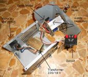
Oh oh oh You get the 'philosophy'of it : less is better .
So...after the mains plug and the mains cable ,the voltage is being reduced (and isolated from the mains) by the transformer ; then the AC becomes DC after the four diodes (graetz bridge) and available almost 'leveled' after the supply capacitor : that's the Power Supply ,the current being calculated by the demands of all the circuits . The fuse breaks if something is going wrong.
Now I see ,the transformer has another secondary... So you basically need transformer +diodes bridge + capacitor and you can supply two amplifiers .
Those are the BA 5417 at pin 9 they receive B+ ,and are mounted on the big board ...later if you need you can type BA 5417 on google and find its datasheet ,to see how the mute and st-by functions are performed ( usually they need a 10 K Ohm resistor to +Vcc , to 'unlock' the amp )....
So Ground connections are important !
Volume control is a different job. Theoretically you could connect a stereo potentiometer ( or two singles) having a value ranging from 10 K to 100 K Ohm ,and you're done ! Practically ,is a different story : moving the cursor ,the central wiper of the potentiometer ,you vary the quantity of series resistance together with the resistance that goes to Gnd,but together with the amplifier's input resistance and capacitance ,it determines a low pass filter (RC) ,so at low volumes (high series resistance and low impedance to ground) you may feel a lack of trebles ...so it is a challenge by itself .
But if your sources provide volume control ...you don't need it
So...after the mains plug and the mains cable ,the voltage is being reduced (and isolated from the mains) by the transformer ; then the AC becomes DC after the four diodes (graetz bridge) and available almost 'leveled' after the supply capacitor : that's the Power Supply ,the current being calculated by the demands of all the circuits . The fuse breaks if something is going wrong.
Now I see ,the transformer has another secondary... So you basically need transformer +diodes bridge + capacitor and you can supply two amplifiers .
Those are the BA 5417
at pin 9 they receive B+ ,and are mounted on the big board ...later if you need you can type BA 5417 on google and find its datasheet ,to see how the mute and st-by functions are performed ( usually they need a 10 K Ohm resistor to +Vcc , to 'unlock' the amp )....So
Ground connections are important ! Volume control is a different job. Theoretically you could connect a stereo potentiometer ( or two singles) having a value ranging from 10 K to 100 K Ohm ,and you're done ! Practically ,is a different story : moving the cursor ,the central wiper of the potentiometer ,you vary the quantity of series resistance together with the resistance that goes to Gnd,but together with the amplifier's input resistance and capacitance ,it determines a low pass filter (RC) ,so at low volumes (high series resistance and low impedance to ground) you may feel a lack of trebles ...so it is a challenge by itself .
But if your sources provide volume control ...you don't need it
hmm........ yeah, i kinda get it, but want to ensure we having the same idea now:
- The 4 diodes bridge you mention serve as a rectifier, is it ?
- So i just unplug the whole power board to use ? or just the rectifier and transformer in that board ? (power board refer to pg.5 in pdf)
- what is the secondary transformer output use to ? (can't understand from the diagram)
- I can't saw the capacitor, or is it included in the power board already ?
- The 2 amplifier in the pdf need to taken out without the circuit ?
Well...... thats quite alot of question X.x But do i use the circuitry of those original (just modfiy a bit) or just take out parts and do the wiring ourselves ?
What do you mean by 'unlock' ? and grounding play a important roles here ? (dont quite get it) Do we need to get an additional resistor or we can take it from the radio player ?
It will take sometime to 'digest' the amplifier structures, but i will try.
Regarding the volume control, i think i will give up (still can find other way to control volume) But there is a volume control IC, can we use that easily ?
and about B+, i still dunno what it is, mind briefly explain to me ?
I hope someone contributes !I will interested to hear others idea and opinion.
Yes ,the capacitor is located on the main board (should be near pin 9 of the BAxxxx amp ).
Groundis 'minus' ; B+ is 'positive' . Before the inputs of each amplifier there's also a transistor ,that goes to ground: I think its purpose is to 'mute' the inputs...and everything is controlled by the logic ,but we are going 'analogical' ...so you must enter the amplifier directly ,skipping everything else.
The extra secondary of the trafo is for supplying everything but the amplifier...just follow the lines (traces on the PCB)...
Ok ,sorry...do you want to see my collection of ripped boomboxes ?
Definitely, very interested ! Gladly to witness your collection !Ok ,sorry...do you want to see my collection of ripped boomboxes ?
So I just regroup all the information together now(correct me if anything wrong):
- I need to dismantle the power board (a circuit with transformer, etc.......), so that i have fuse, along with the rectifier.
- I need to unplug the 2 amplifier IC (BA5417) from the circuit for assembly usage
- The 2 big speaker (most important element? X.x)
And thats all things i need from the radio player ?
If that so, how should them be wired up to each other ?
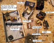
Now I'm gonna be thrown out from the Hifi community ...
All these ICs are very low power and exhibit high distortion rates when
pushed hard ,nevertheless some can drive also simple speakers ...
the TDA7394 is the latest find and the best !! See how the PCBs are intact for their function ...you don't have to extract the chips from them !!
I have also some potentiometers around ...I think it costs less a digital control (volume ,tones, input selector ) than the good old switch or variable resistor ,which of course have metallic parts that oxidize .
Hey ! I have that BA 5417 ! it is only one chip ,does stereo because each amp is Single Ended -it is output capacitor coupled- and yours are two 'cos they operate in Bridge Tied Load (more than double the power -must sound good !)
I would say the last thing ,before operating ...
You can try to do the first mod ,which is to cut that connection to/from the CD and put two RCA or one 3,5 mm stereo jack (T.R.S ).
If everything is done right , when selecting CD you should hear your new source. Then ,if you are confident ,you can cut out all the circuitry you don't need .
Different address for the speakers ...
Attachments
- Status
- This old topic is closed. If you want to reopen this topic, contact a moderator using the "Report Post" button.
- Home
- General Interest
- Everything Else
- modification to my old radio