Some pics of the new Revision C board installed in a another Oppo981. This is the second Oppo that I have installed the board in. The first one went into the player with the coax out option that the rev B board was installed in.
This pic shows how I have wired my board into the connector location next to the Oppo DAC chip. I have kept the wires very short to minimize inductance and signal degradation.
The pic also shows where I have removed the Oppo crystal along with two caps and a resistor. The original Oppo design is a common two inverter oscillator with crystal, two caps and a resistor. I have wired my 27M clock to the pads of where the cap was on the first inverter input. I am using the green and black twisted pair.
http://home.columbus.rr.com/rossl/images/mod/revc_mod1.jpg
This pic shows the back end of the mod. Instead of installing an XLR jack in the Oppo, I cut the female end off of a standard 110 ohm AES/EBU cable. I drilled a hole and inserted a grommet. I wired the cable directly to the output of the digital audio output transformer.
http://home.columbus.rr.com/rossl/images/mod/revc_mod2.jpg
I have now tested the coax out option and the AES/EBU out option. I still haven't tested the optical out option. The AES/EBU option with the cable is easy to do and if your DAC will accept the XLR cable then I recommend doing it. Coax would be my second choice and Toslink would be be the fallback plan.
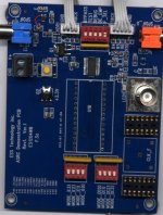
Another view of the entire mod. Power comes in at the top of the pic.
http://home.columbus.rr.com/rossl/images/mod/revc_mod3.jpg
Anyone who wants a bare board, please contact me within the next few days so I will know how many boards to order.
My email is in post 78
http://home.columbus.rr.com/rossl/images/mod/revc_mod3.jpg
Anyone who wants a bare board, please contact me within the next few days so I will know how many boards to order.
My email is in post 78
elecon said:
rossl
As of today March 22, your e-mail is still turned off in the control panel

Hi elecon,
Please send me an email about ordering the circuit boards. My email address is in message 78.
I believe I'll pass until you have enough to go around. It wouls be wasted on me since I will have to get some one to stuff it for me. If you have several (enough anyway), that would be different and would want one ... how are the tests going? 
(Yes, your email is off from DIYAudio.com)
(Yes, your email is off from DIYAudio.com)
DVD player mod bare boards
I have the following people who want the bare boards:
4 boards - jims
1 board - TedS
1 board - Sergio
1 board - busyx2
1 board - Hans
The cost is $15 per board. Then I will send the board with schematic by Priority Mail for $5.
International Priority mail is $5.25
The boards take two weeks, so if I can order them on Monday, they will arrive here on April 17 or 18.
I have sent you all an email for ordering.
FastEddy said:... how are the tests going?
It sounds even better after the crystal oscillators have been running nonstop for a week.

Hi everyone, and Rossl in particular!
I have mailed my order for 5 (five) x boards to the address given in mail #78. I tried this before, but realized that I made a typo when writing the rossl part of the address with a single "s"... (so my mail bounced)
Oh well! Hope my mail gets there in time before you place the total order to the board house!
Thanks Rossl for making this project possible for all of us to participate in!

slightly off topic
rossi: I have in my possession an ASRC demonstration board from ESS Technology. It has coaxial SPDIF I/O ports, data lines I/O, BNC connector for analysis and other support for I2S 24 bit work ...
With the permission of ESS Tech, I have the authorization to find this a good home and this seems to be right "up your country". ESS is interested in seeing this circuit evaluated as a part of DIY kits or commercial endeavors ... Please email me and I'll send it along ...
(My tired old eyes / intellect / ablities / work load just don't have the levels required to follow through on this.)
Attachments
While we are waiting a few more days for the order of PCBs to arrive, jims is building up one of the boards that I purchased in the first batch last month.
A couple of questions from Jim:
1) what is the advantage of removing the crystal from the oppo board
answer-
The 27MHz clock on the mod board replaces the Oppo crystal. The DVD player retains full functionality. The new 27MHz oscillator is much better than the cheap 15 cent crystal that Oppo uses in terms of jitter and frequency stability. Also, it is not a good idea to have two individual 27MHz oscillators in close proximity, since they could interfere.
2) the way I understand it the jumper is for either 96K or 192K, should you experiment with the jumper at different frequencies depending on the source? If so should I wire in a switch?
answer-
I soldered in a wire to jumper for 96K. My DAC doesn't accept 192K data. Choose one or the other and hard wire it. I suggest using 96K, unless you are sure your DAC can receive 192K. If you put in a switch for output frequency you would also need a way to reset the Cirrus Logic chips... like adding a reset button.
3) suggestion: on the layout it might be a good idea to indicate with an asterisk those components that will change depending on the output you want (toslink, aes or coax).
answer-
You are correct, the bill of materials does not include parts for whichever output option you choose. There is nothing on the PCB silkscreen legend that specifies if a component is installed or not. For the coax option, you will need a 240 ohm 0805 resistor and it is not on the parts list.
4) I have a clock on my dac, is it a problem to have an additional clock?
answer-
The mod will operate independently of the clock on the external DAC.
5) I want to clean the board, are all of the chips able to take 95% Isoprop.?
answer- yes
6) Just an update on the board. I almost have it finished. I have about 2-3 hrs of work on it. Great design, very high quality board, and easy to solder. A couple of suggestions:
I forgot about the polar caps, so I had I got a couple backwards. It might be a good idea to put a "+" or a darker line on the schematics and maybe a note. I also think you really have to start with the chips and then the resistors and finally the caps. At least that worked best for me. Maybe a note to that effect if you feel it is generally a good idea.
answer -
I did a few tests with the ohm-meter before I soldered in the board. I just wanted to make sure that power wasn't shorted to ground. I also double checked to make sure the chips, the oscillators, the diodes and the tantalum caps were soldered in the correct direction.
- Status
- This old topic is closed. If you want to reopen this topic, contact a moderator using the "Report Post" button.
- Home
- Source & Line
- Digital Source
- Mod for DVD player Hi-Rez stereo PCM output - SACD DVD-A HDCD