Still reading up on REW, I don't like the curves I'm seeing with pink noise. I have 2 other sources to compare to with Dayton mics. One, a mini Dayton mic plugged into a droid tablet using the Advanced spectrum analyzer app, which shows a level response from low midrange to 20Khz. Another, the built-in RTA on the DEQ2496 with a calibrated Dayton mic, shows the same. REW is showing the FR falling off into the upper range. I don't trust it, and the calibrated file for the mic has been downloaded and linked.
Update: Ordered some mini bubble inclinometers for the speakers so I can precisely angle each speaker. Took over an hours worth of searching. I knew what I wanted, just not the proper search terms. Also, will soon order some planar super tweeters to experiment with. The current AMT's are OK, but I'd like to compare them to another option.
Update: Ordered some mini bubble inclinometers for the speakers so I can precisely angle each speaker. Took over an hours worth of searching. I knew what I wanted, just not the proper search terms. Also, will soon order some planar super tweeters to experiment with. The current AMT's are OK, but I'd like to compare them to another option.
The better way to see the FR at the measuring position is to use a measurement sweep in REW rather than the RTA. The RTA works well for a Moving microphone technique where you sweep the mic around your listening area and it averages the response.
Press measure, SPL and set the sweep limits corresponding to half your sampling rate or less at the top. 1M is the longest single sweep which should give the best signal to noise ratio but often the shorter sweeps work fine.
If you have a calibration file you can tell REW to use it but it will only have an effect in the SPL window after you save the RTA or sweep measurement.
Another simple technique you can use to see how even your bass response is to sit where you will listen and sweep the sine generator up and down between 20 and 200Hz, that will let you hear if you have any severe modal peaks and nulls and where they are. Change the position of your speakers and check for improvement.
The better way to see the FR at the measuring position is to use a measurement sweep in REW rather than the RTA. The RTA works well for a Moving microphone technique where you sweep the mic around your listening area and it averages the response.
Press measure, SPL and set the sweep limits corresponding to half your sampling rate or less at the top. 1M is the longest single sweep which should give the best signal to noise ratio but often the shorter sweeps work fine.
If you have a calibration file you can tell REW to use it but it will only have an effect in the SPL window after you save the RTA or sweep measurement.
Another simple technique you can use to see how even your bass response is to sit where you will listen and sweep the sine generator up and down between 20 and 200Hz, that will let you hear if you have any severe modal peaks and nulls and where they are. Change the position of your speakers and check for improvement.
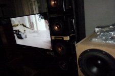
The sub config needs help I know... Thinking downfiring for 4 of the 8 in corners
Testing new tweeters currently.
Attachments
Mio
But in this case theyre only being used from 13kHz. They're definitely 'brighter'. Also 6ohms.
Ribbons act like mini line arrays. Mounted like you have them, the horizontal dispersion will be very limited. You will need to angle them directly towards your head which will probably make the sweet spot very narrow.
But in this case theyre only being used from 13kHz. They're definitely 'brighter'. Also 6ohms.
Last edited:
I'm not happy with it currently. It's very bright and the lobing effect is back, like when I had the Pluvia's stacked straight with no tweeter. I'll try mounting these tweeters vertically next and maybe a 1.5uF cap instead of a 2.0uF.
Perceval and everyone, thanks for your observations.
EDIT: The inclinometers were trash. The little steel balls did not roll very freely inside the plastic housings.
Perceval and everyone, thanks for your observations.
EDIT: The inclinometers were trash. The little steel balls did not roll very freely inside the plastic housings.
Last edited:
Mounting the these planar tweeters vertically gave a very small sweet spot. Moving head up or down made the highs disappear quickly. Googled planar/ribbon tweeters and found this was to be expected. Oh well, they were cheap. Going back to the Dayton AMT's and just going to enjoy the system for awhile.
Quick update as things are changing soon.
First, a few notes after 2 months of listening:
The bottom 2 on the left and right SB Acoustics 8" sub drivers are finally broken in. I know this because I was listening to a very familiar musical track and the bass was WAY too much, and this seemed to be a very sudden transformation over maybe the last 2 weeks or so. Watching Alien Covenant 2x at moderate to plus levels may have done it. Difficult to tell as all kinds of audio sources go through this speaker setup. Enough of that...
I got an itch to totally redo the enclosures of the P7s, which currently number 16 @8/side. I got the itch from Dave @ Planet10 who posted THIS on another thread. With a tighter enclosure, I'm aiming for a total 14 P7's per side. This should still allow for about a 1" space between each driver enclosure on the 7ft towers. Not much of an angle, but I'm willing to give it a shot for something better.
If you are planning to put them in pipes like in that picture that will create a circular baffle which is one of the worst shapes for diffraction without any round over added to smooth the transition, if that is of any concern to you, maybe not.
woops, I see you're correct after reading about edge diffraction. What a n00b I am. I used a router to roll the edges of these boxes just so it would look good, without even realizing it aids in a smoother FR.

EDIT: But then again, I wonder how the gaps between each box affect diffraction.
I think I'll stick with the current design which has enough room for 4 more P7's per side.
I have to avoid a single large enclosure because I have to be able to disassemble/assemble them. You see, I made a deal: No bitching about my speakers and you get hardwood floors. No bitching (not too much anymore), so the time is coming soon.Maybe better to have a single baffle with all your openings into it and glue in the pipes onto the back of the baffle?
A little like wesayso's cosmetic aluminium supra baffle.
Thanks for all your input fellas!
Last edited:
Sceana speakers
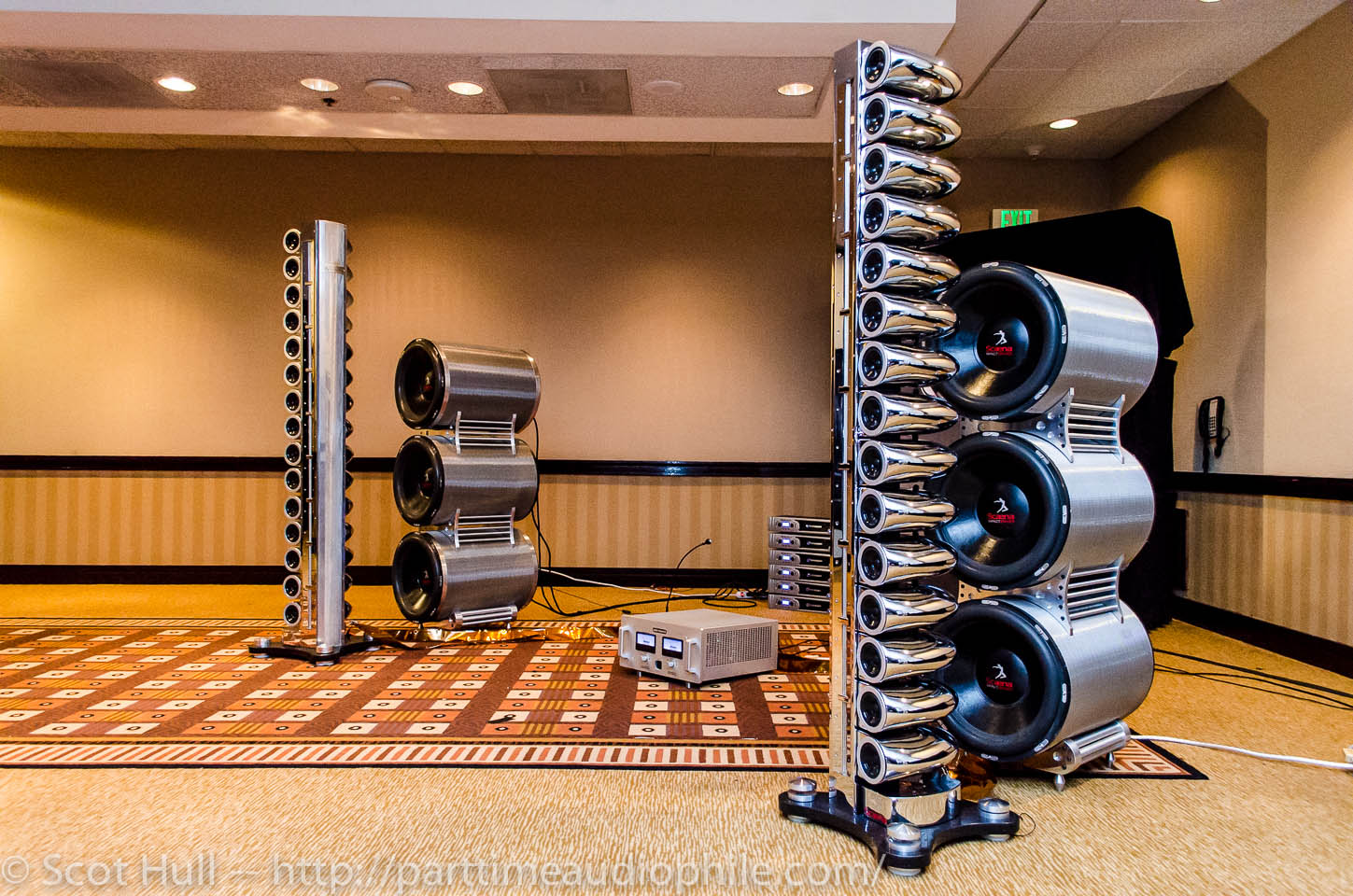
dave
Yes! The Scaena's! My model
I've seen that pic before. I believe it's their Silver Ghost model. Looking at it, with the FR drivers in front of the subs, makes it almost a coaxial type design...
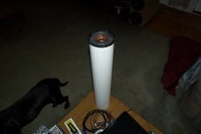
I decided not to dive in and get all the parts. Since I'm at least going to add 4 more P7's, it makes sense to get the 4xP7's and 4 PVC enclosures and do a listening test with a breaking in period for the P7s of course. It was only $50US for 4xPVC enclosures.
So for each enclosure I'll be using 2 Ft long 4" white PVC (I was eyeing more expensive black ABS), a 4" cap for the rear and a fem-fem coupler for the front. Once I cut each coupler in half, hopefully it will slide right over the front, it will bring the width out to 5".
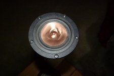
Here's why I need the fem-fem coupler in order to properly mount the P7. It's function is to expand the mounting surface to 5". Sorry for my imperial measurement spec's AND the terrible pics... BTW that is one of my damaged P7's which was my fault early on in the build, but I kept it. Thankfully so.
Attachments
Dave, quick question: for a volume of .175cuft (24" long 4" diameter cylinder), what would the F3 & F6 be?
and what about a half size .0875cuft (12" x 4" cylinder) F3/F6 for the P7?
...I can't have a 2ft long cylinder for the final construct, I may be drifting towards a larger driver like the Alpair 10M for a great many reasons, except cost.
I don't mean to task you, but thanks if you can spare a few minutes! You have in the past.
It's all going to rest on how these new P7's sound in these enclosures arranged in a super-mini array. This is how I got to this point in the first place, although with square MDF boxes...
So abit of history repeating itself here, but definately headed in a certain direction.
Cheers!
Last edited:
- Status
- This old topic is closed. If you want to reopen this topic, contact a moderator using the "Report Post" button.
- Home
- Loudspeakers
- Full Range
- Mini Tower Line Array using Pluvia 7's