Hmmmmm. I'll have to mull this over. How would the dispersion compare to a single larger driver like the PA130?
There is a seller on Amazon that will do a pair of the 3FE25 for $38 shipped, not too bad.
I set up the .041x K's in their (temporary)permanent spots on either side of the TV, about ten feet apart, up against the wall. They are about halfway up the wall on a couple tables due to our strangely arranged living space, as I would prefer them lower, but this keeps them away from my little man. They sound superb. I'm not sure if it's just because they have more "breathing room" on either side, or just because of the surroundings but they have fantastic imaging and quality. They have great dispersion around the room for music, and an almost surround-sound sort of quality (without sacrificing stereo imaging) to them, fantastic for watching movies. These would make excellent home theater satellites in a moderate to large sized room in my opinion.
Speaking of increase efficiency for flea-watt tube setups, my current 1 watt per channel amp has no problem pushing these past reasonable listening levels. Sounds like a challenge to build an even smaller push pull amplifier. I've got a design in mind that uses subminiature pencil tubes that will do 1/2 watt per channel, all in the footprint of a credit card. Just have to figure out some smaller transformers to fit it all in a nice chassis.
Last edited:
Lingwendil,
When you put some space between the speaker and the back wall, the imaging will become wider than the physical separation of the speakers. It’s kind of a neat effect I first observed when listening to the 0.40x K’s in the middle of the room.
I saw your 1w tube amp. Very cool and love the use of re-purposed $10 Antek donuts for high-fi tube outputs! That has me thinking. Maybe I could use one for the inductive load on my SE Class A headphone amp?!
If you get four of the 3FE25-16 from the usual place, add $24 more and it’s free shipping. Easy to do with needed speaker building accessories. Banana jacks, binding posts, and crimp female spade terminal will fill that up pretty quick. That’s how they get you with “free shipping” though.")
When you put some space between the speaker and the back wall, the imaging will become wider than the physical separation of the speakers. It’s kind of a neat effect I first observed when listening to the 0.40x K’s in the middle of the room.
I saw your 1w tube amp. Very cool and love the use of re-purposed $10 Antek donuts for high-fi tube outputs! That has me thinking. Maybe I could use one for the inductive load on my SE Class A headphone amp?!
If you get four of the 3FE25-16 from the usual place, add $24 more and it’s free shipping. Easy to do with needed speaker building accessories. Banana jacks, binding posts, and crimp female spade terminal will fill that up pretty quick. That’s how they get you with “free shipping” though.
Last edited:
Overspec them for good low end response, and run them parafeed or keep the DC through each half even, and they are wonderful.
Might as well use a few tubes though if running output iron
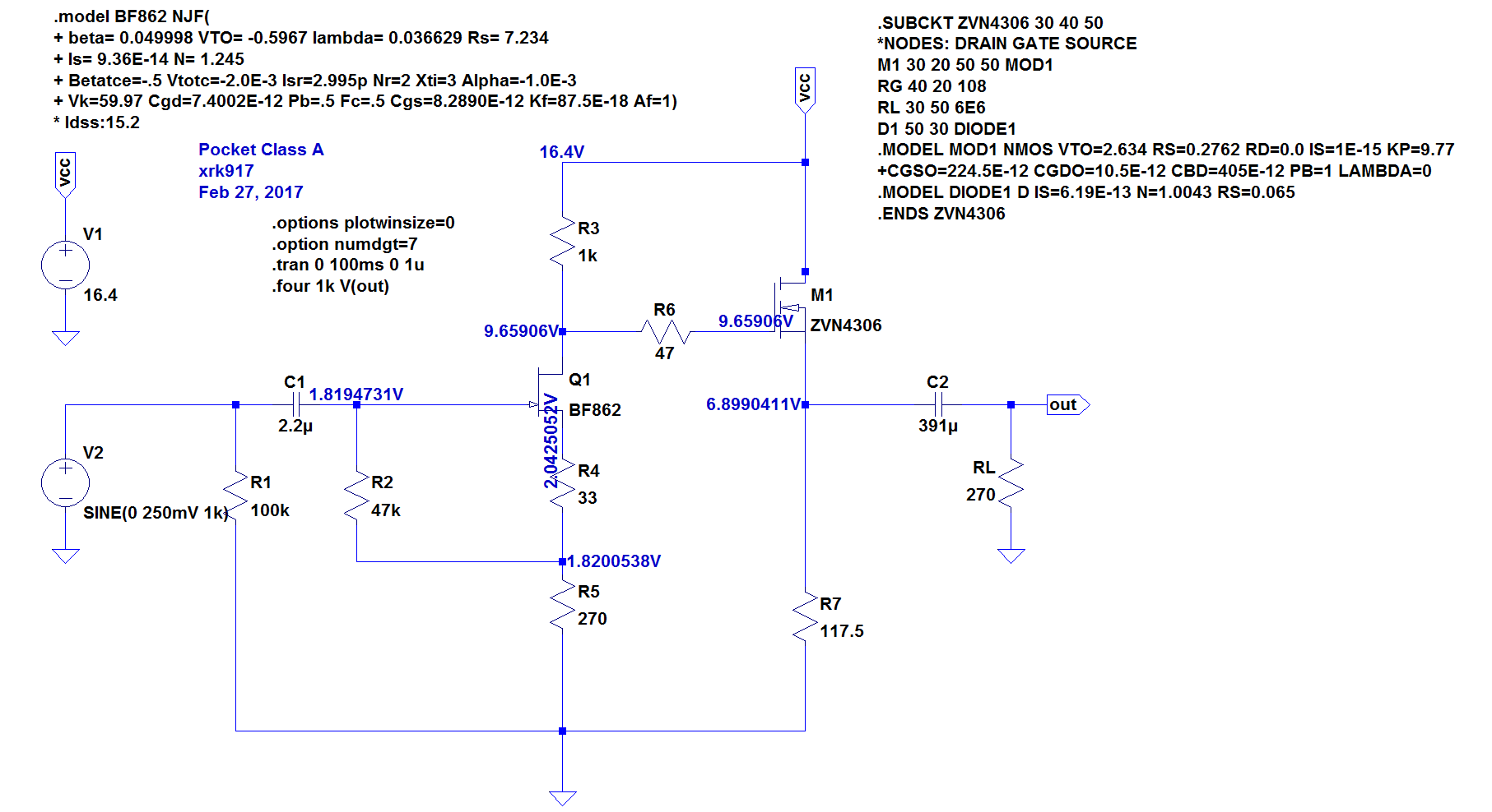
New term to me: parafeed. I want to to use it as a choke with DC bias of about 70mA to 100mA and would like about 20mH to 50mH (or more) and low DCR.
Basically it will go where R7 is in the schematic below. I will of course, readjust DC setpoints for proper bias current.
It’s OT so if you want we can take this over to the proper thread here:
xrk971 Pocket Class A Headamp GB
It would work if you run each half of the primary as you would each half of a push pull transformer, but not as you mention, the standing DC current will saturate the core since there is no airgap. You could run each half as a load off of a separate amplifier as a fully balanced config though. SE doesn't work with regular toroids.
Does that make sense?
A bit off topic though... So if you wanted to bring It over there I may not have much else to add, having fallen hard for tubes long ago...
Does that make sense?
A bit off topic though... So if you wanted to bring It over there I may not have much else to add, having fallen hard for tubes long ago...
Well, ordered the set of four 3FE25-16.
I was going to do an order from Parts Express, but I'm pretty well stocked on most of what I can get from them, and I need to order some stuff from Mouser or DigiKey soon anyway.
Time to go pick out more black foamcore, my GF really likes how the black looks on the smaller K's. Might go to the craft store and see if they have any purple to match my next amplifier build, black with purple for the interior where the speaker mounts would look slick
Did some looking through the thread for details on the x0.53 build. Looks like I should use XRK's original size modifications (note that the recent 3FE25 version drawing appears to be true x0.53 scaled). But what about bracing? There's some pretty good bracing going on in post 33 (XRK's origianl build), but I'm not seeing as much in other posts. I could just use the same as the x0.4. Any opinions?
Did some looking through the thread for details on the x0.53 build. Looks like I should use XRK's original size modifications (note that the recent 3FE25 version drawing appears to be true x0.53 scaled). But what about bracing? There's some pretty good bracing going on in post 33 (XRK's origianl build), but I'm not seeing as much in other posts. I could just use the same as the x0.4. Any opinions?
What is the difference between the "true" x0.53 and the XRK original?
What is the difference between the "true" x0.53 and the XRK original?
When I scaled the plans by 0.53x, I made some small adjustments to make it easier to measure and cut with natural ruler lengths etc. Here is the "xrk971" scaled plans from post 1.
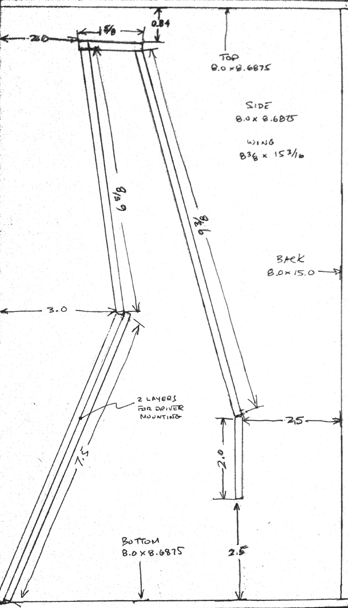
vs a true 0.53x taken by meticulously rescaling the GregB CAD plans as done by Blades and Mudjester, etc.
The design is very forgiving so a few mm off here and there is no big deal. Even +/5mm (except on vent width) is OK. Don't fret - jut build.
Not really meticulous for me. Since I'm using SolidWorks I just drew up GregB's original, then scaled it. Then I made the foam core panels, constrained to one side or the other of the original walls depending on what dimensions seemed more important (you can see this in the red line overlay in the x0.4 plans). Since I already have the model from making the x0.4 plans it would actually be easier to just re-scale to x0.53. However, it looks like many of the successful builds used XRKs original modifications. I don't want to change what's been know to work well. The only potential down side for my plans is I'm going to design a score-and-fold version and I don't know if that'll fit on the 20x30 panels as well. I could try it both ways, but that'll take twice as long since planning the cutouts isn't fast.
Hi Mudjester,
Thanks for making the CAD plans. I think it would be perfectly safe to use the GregB drawings scaled to 0.53x vs “xrk modified” plans. The design is quite forgiving and a few mm here or there is no big deal. If you could make it oprimized for 20in x 30in foam core stock that would be a bonus. But don’t work too hard on that. We know that standard 20x30 sheets work. They just may not be so easy to do a long span of score and fold. Definitely the long run from the internal divider to the front driver mount panel and panel above is possible on single 30in length. Then the bottom panel, back panel, and top panel are one more run.
Thanks for making the CAD plans. I think it would be perfectly safe to use the GregB drawings scaled to 0.53x vs “xrk modified” plans. The design is quite forgiving and a few mm here or there is no big deal. If you could make it oprimized for 20in x 30in foam core stock that would be a bonus. But don’t work too hard on that. We know that standard 20x30 sheets work. They just may not be so easy to do a long span of score and fold. Definitely the long run from the internal divider to the front driver mount panel and panel above is possible on single 30in length. Then the bottom panel, back panel, and top panel are one more run.
Last night I was looking at exactly that. Turns out the top, bottom, and back together are over 30" for either design. I'm planning on having only the bottom and back joined, then have the top a separate panel (although it could go the other way too since the top and bottom are the same). Overall, it should make the build easier that way anyway, because as one piece the score-to-score distance in the back piece would be more critical to get it all to line up properly with the other panels. Having a L with a separate panel (like the x0.4) will make it easy to adjust for any errors during build.
Ooooh, how's this for an idea: I could have the top and back one piece, the internal divider one piece (as I showed before), and then make the bottom with a doubler for the driver mount. I think that would make it even easier to build. I find the folded pieces easier to position since they stand up straight on their own, I don't have to use a square to position them during the hot glue phase.
I actually had started questioning my sizing when it came to the aperture. The true scaling is a fair amount taller. I inserted your drawing into my sketch and scaled it up, but I wasn't sure that was the right way to do it. The initial gap came up to 0.4" wide. I know the position and width of that gap are important, but I wasn't sure how to constrain it.
So, I'm at the local Hobby Lobby (man I hate this place lol) and they have the foam board in white and black in a 1/2" thick version for $6.99 a sheet. I figure I'll grab one and see how it sounds for the front wing, or even just for making mounting cleats with and other experiments. Two layers of 3/16" stuff is of course stiffer, but I think for this purpose the 1/2" would work well enough.
No purple though
All black it is, I suppose. Unless the other craft store (Michael's) has some in purple.
No purple though
All black it is, I suppose. Unless the other craft store (Michael's) has some in purple.
You should check Joann's if you have them there.
Elmer's Foam Board 20"X30"X3/16"-Purple | JOANN
Elmer's Foam Board 20"X30"X3/16"-Purple | JOANN
The only one around has white and nothing else.
Black it is.
10 pack of Elmers (good stuff) in any color you want for $6.30 ea. shipping included if you are Prime member.
Amazon.com : Elmer's Colored Foam Board, 20 x 30, Red, 10-Pack (950052) : Foam Boards : Office Products
- Home
- Loudspeakers
- Full Range
- Mini Karlsonator (0.53X) with Dual TC9FDs