Yes.tcqanh said:Cinput = C-Miller + Cgk + ...
You can't. As I said, calculating it is easy; finding the values to put into the calculation can be difficult. If you can't calculate it then you have to measure it. The main effect on your circuit will be to impose an HF rolloff. If you can measure that (or its time domain equivalent, as Marcel suggests) then you have what you need.If we have no data of Cinput at triode mode, or also no data of Cg1-g2, then How do we calculate C-Miller ?
I usually find capacities of the three elements individually, to the rest tied together.
I would thus guess that input capacitance is g1 to all the rest tied together, output capacity the anode to all other electrodes tied together, and Miller effect as a result of 'g1 - a' capacty.
I would thus guess that input capacitance is g1 to all the rest tied together, output capacity the anode to all other electrodes tied together, and Miller effect as a result of 'g1 - a' capacty.
A problem with this method is that it gets inaccurate when the capacitance to be measured is small compared to the probe capacitance, as is probably the case with Cg1-g2 of a valve.
Best is to do it in-circuit, so you measure the full input C including Miller. If you want Miller separately, you can back-calculate.
Correct.
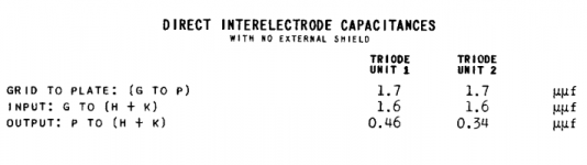
But as said above the input source sees the total capacitance in a built-up circuit. E.g. fractions of pF will result from the tube socket; the grid and anode pins are adjacent. Particularly where the values are low as above one can best get it accurate by measuring frequency response in situ. This must of coarse include relevant resistances - a capacitor does not affect frequency response on its own. This includes the impedance of the input device, etc. (Just slapping on a signal generator with an ouput impedance of say 600 ohm will give too favourable results compared to most input devices.)
But as said above the input source sees the total capacitance in a built-up circuit. E.g. fractions of pF will result from the tube socket; the grid and anode pins are adjacent. Particularly where the values are low as above one can best get it accurate by measuring frequency response in situ. This must of coarse include relevant resistances - a capacitor does not affect frequency response on its own. This includes the impedance of the input device, etc. (Just slapping on a signal generator with an ouput impedance of say 600 ohm will give too favourable results compared to most input devices.)
No. Valve datasheets generally give capacitances with all other electrodes grounded, so there is no Miller effect. For circuit design you won't have other electrodes grounded so you will get Miller effect.Now, look at the Tungsol 12ax7.
Cinput = C grid to (Kathode + H)
Couput = C plate to (K+H)
So, Cinput = C-Miller + Cgk, is it right ?
Cinput (in circuit) = Cinput (from datasheet) + Cmiller
OOPS!!
Of course. I fear I am so used to read Cgk as actually Miller effect, that I faulted on things here. That also why I followed by provisions, which would include Miller effect. No, it is (Cgk x gain); but effect best measured in circuit to include everything.
Sorry about that (obviously not at my best before bed-time,)!
- Status
- This old topic is closed. If you want to reopen this topic, contact a moderator using the "Report Post" button.
- Home
- Amplifiers
- Tubes / Valves
- Miller Capacitance of triode strapped pentode