More
Have a look at this thread as well:
K402 Fact Sheet - 2-Channel Home Audio - The Klipsch Audio Community
To access the important attachments you will need to register/log-in. WHG
Have a look at this thread as well:
K402 Fact Sheet - 2-Channel Home Audio - The Klipsch Audio Community
To access the important attachments you will need to register/log-in. WHG
Yeah. The K402 looks like a GREAT midrange horn. But it's too large for my living room, despite the explanation by Roy as to why a large horn is better for small rooms acoustically speaking. I'm sure he's right, but can't. I wish there was a smaller version of this horn as I don't need it to get to 200Hz. The K501 is an earlier model and the 402 received significant improvements.
But reading this and Geddes is making me come to some common denominators: conical expansion for constant directivity/coverage, smooth transitions at the mouth towards vertical and horizontal (tractrix for 402), smooth large radius transition from throat to conical.
But reading this and Geddes is making me come to some common denominators: conical expansion for constant directivity/coverage, smooth transitions at the mouth towards vertical and horizontal (tractrix for 402), smooth large radius transition from throat to conical.
Two to Go!
Before you throw the baby out with the bath water, you should be aware of two facts:
1) The K-402 was designed to work not out of a room corner. With corner placement a diminutive version is possible without sacrifice in performance.
2) The Jubilee bass bin does not require corner placement to provide an acceptable performance. Of course the closer to adjoining walls it is placed the lower it will go without equalization. However, making it smaller is not a tenable option.
Regards,
WHG
Last edited:
The K-402 is not an option for me. I realize it's a great horn, but not for my needs.
Phase plug is in the cards. I first need to establish the geometry of the throat I'll be working with.
The driver is 5", and the cloth suspension diameter is 4.3" (the smaller diameter, where the paper cone ends and the first cloth bend is placed). The largest diameter of the suspension is 4.84", where the seal gasket starts.
Right now I'm using an 18mm MDF plate between the driver and the conical expansion. I tried a circular opening (throat) and now have a larger square throat 3.35x3.35" (85x85mm), with rounded edges towards the driver. Larger opening worked better. The conical expansion starts at 85x85mm and expands onto a rectangle.
I was leaning towards eliminating the 18mm plate between the driver and conical expansion (to minimize throat volume) and start the expansion at 4.3x4.3" square (the smaller dimension of the cloth suspension). And later experiment with phase plugs.
After reading Geddes on waveguides, I'm also considering keeping an MDF plate between driver and conical expansion, but to have a circular opening in the plate with OS expansion for the first 15 to 20mm, then hand over to the conical expansion. If I were to go down this path:
- Which should be the starting diameter of the OS profile? 4.3"?
- The transition from circular OS to square conical...I will need to adjust manually with filler. Should I make the square S1 the size of the OS diameter by the end of the plate, and fill in the corners?
- And later experiment with phase plugs
A phase plug isn't always used with a cone/mid arrangement, although one could be used to define any exit angle needed, in theory but there are often constraints in a design. Said angle would be, for example, the relative angle of radii bounding a spherical cap.
Needing some clarification. What is the relative angle of radii bounding a spherical cap?
Relative what to what? Angle of radii? Angle of which radiuses?
Compresion Ratio
[Sd]/[St], needs to be determined first.
Use David's program and do some simulations. Based on driver excursion limits you need to calculate front cavity volume minimum as well. Note you may be able to tweak this volume to give you a response boost at the upper frequency end where you are already dealing with mass roll-off. Once you have picked the ratio, and set front cavity volume, then its time do address the phase plug / transition geometry needed to implement it. WHG
(Apologies for the randomly acquired image)What is the relative angle of radii bounding a spherical cap?
Defining an exit angle includes deciding on a wavefront shape, creating and holding that shape over a given bandwidth. Spherical might be the most common choice, partly because drivers are usually round.
If the angle is non-zero, the wavefront has depth (a sperical cap). The subtended angle of radii that are normal to an arc across the cap define also the virtual source point of the wavefront.
Conicals don't load well at lower frequencies. This isn't to say that the waveguiding becomes incorrect so there is still benefit to considering the shape at lower frequencies, but it also becomes less of a critical issue at lower frequencies, possibly allowing compromises.His waveguides are intended to be used from 900Hz and above.
Just a natural choice for a freestanding extension to a round compression driver, etc..Everybody's talking about axis symmetrical waveguides. Easier to build and design.
These are not a phase plug.Interesting idea of foam phase plugs to absorb HOMs.
You are making arbitrary calls in a complex situation here. Sometimes close enough is good enough, other times not. With regards to the size of the opening in the plate, consider whether it is offering you a chance to improve your situation such as delaying the wavefront edges vs the centre, making the opening smaller so it it closer to a point source at a higher frequency etc..Which should be the starting diameter of the OS profile? 4.3"?
- The transition from circular OS to square conical...I will need to adjust manually with filler. Should I make the square S1 the size of the OS diameter by the end of the plate, and fill in the corners?
- And later experiment with phase plugs
Attachments
[Sd]/[St], needs to be determined first.
Use David's program and do some simulations. Based on driver excursion limits you need to calculate front cavity volume minimum as well. Note you may be able to tweak this volume to give you a response boost at the upper frequency end where you are already dealing with mass roll-off. Once you have picked the ratio, and set front cavity volume, then its time do address the phase plug / transition geometry needed to implement it. WHG
OK, I'm biting the bullet. Let's hope I get to the other end with intact teeth

I went back to centauraudio.com.au to revisit phase plugs and played a bit with drawing a cross section (boy, do I miss having AutoCad!!) and Hornresp. What you see below is far from optimized, but rather to confirm if I'm the right path.
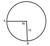
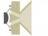
- First picture is a cross section of the driver + axisymmetrical conical phase plug and matching throat + 90 degree conical horn.
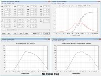
- Second picture is the Hornresp output for this driver and conical horn, without phase plug. Notice Vtc is 100cm3, which is my estimation of the volume in front of the cone and before the conical expansion. Note Atc=94cm2
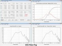
- Third picture is same, but with phase plug. Now Vtc is same 100cm3 + volume of the conical cavity in the throat - volume of the conical phase plug. While the phase plug takes volume away, it is less than what is added by the throat...Also note Atc is 32cm2
At these frequencies, am I right to look at coustical pressure rather than acoustical power?
Am I sort of kind of on the right path?
FWIW Sd/Atc=2.94. High, low?
One way to reduce Vtc is to make the phase plug shorter, but I'm thinking that would create higher turbulence at the exit. Should I make the phase plug longer?
Another way to reduce Vtc is to make the space between phase plug and conical throat thinner.
Attachments
If this curve is correct, it will tell you how to fabricate the horn. Just "read" the curve !
http://www.faitalpro.com/products/files/M5N8-80/12/M5N8-80_curves_12.pdf
http://www.faitalpro.com/products/files/M5N8-80/12/M5N8-80_curves_12.pdf
Indeed! Thanks for catching that! It was not intended, but rather a mistake. The Hornresp model I belive stays the same. I will adjust the drawing.I think the cross sectional area at the 'pinch' will be less than that at the cone end of the throat, is that intended?
I'm afraid I don't know enough to do that. What do you read in that curve and what does it tell you about how to build the horn?If this curve is correct, it will tell you how to fabricate the horn. Just "read" the curve !
http://www.faitalpro.com/products/files/M5N8-80/12/M5N8-80_curves_12.pdf
Is it correct that the phase plug acts primarily as a throat chamber volume reducer?
From the picture, it seems that it would also act as a port between the throat chamber and the horn. In HR you can model a sealed chamber as "throat ported" and then the length of the phase plug becomes the length of the throat port. You can model different lengths and find an optimum or best tradeoff.
From the picture, it seems that it would also act as a port between the throat chamber and the horn. In HR you can model a sealed chamber as "throat ported" and then the length of the phase plug becomes the length of the throat port. You can model different lengths and find an optimum or best tradeoff.
Is it correct that the phase plug acts primarily as a throat chamber volume reducer?
Well, that's only one part of what it does, a smaller chamber extends the bandpass function of the horn at the upper end.
It mainly reduces the phase differences (-> dif. distance) between different parts of the membrane to the throat of the horn.
Phase Plugs
The phase correction elements of a compression driver work the same way, it's just mechanical differently realized.
Hornresp assumes a plane wave at the throat. It appears to be able to model diffraction thereafter, with some models at least.. I have to admit to being a little unsure of the capabilities here but I don't take it to chance anyways.The Hornresp model I belive stays the same.
I guess you could assume a plane wavefront at your throat but the horn you have might not maintain that. You may have the right expansion, which is one thing at the low end but at the high end the phase plug is there for more than filling in the volume in front of the cone as the hornresp models are showing.
Hornresp has a wavefront simulator that might show this?
right but volume reduction was the only effect that I could see being modelled
How should I model the rest?
I'm afraid I don't know enough to do that. What do you read in that curve and what does it tell you about how to build the horn?
Well, the first thing to verify is, IF the published response curve is accurate.
But, let's just assume it is, for the sake of this (brief) discussion. It's pretty nice, just as it it is, yes ? I can further develop on this curve, that a 5 inch loudspeaker on a flat baffle/direct radiator configuration will simply not sound natural in the lower mid range-range. That's where a horn/wave guide can come to the rescue. In this way, only the lower part of the spectrum needs "help".
In my opinion, and based on many years of experience, you really don't need much in the way of a conventional horn here. You simply needs some "wings" to lift up the lower register. If it were me, I would calculate what it takes (size wise) to support at least a 300Hz wavelength, assuming you might like to cross as low as 400 Hz, you would need about 2/3 of an octave support in order to maintain a somewhat liner phase response. The last thing you need is a small throat, or an obstruction in front of the cone. Just my thoughts.
Best regards.
- Home
- Loudspeakers
- Multi-Way
- Midrange horn design, cone-driven - 201