Mooley,
April fools Day !
Did you see my attatched picture !!
I did
")
But it's only March
... well up here it is anyway lol.Well that's great that you have modded it successfully. It's worth checking the DC offset at the output sockets, it should be as close to 0.00mv as you can get it (by adjusting those multiturn trim pots, one for each channel). Anything under a couple of millivolts is fine and it will drift a little as it warms up (and the case is on).
Pleased you like it... I think the sound is improved over the NE5534's (in mine)
Power cables... I'm not a believer
The PSU and it's regulators/layout/grounding etc determine the quality of the supply. A metre of some weird cable isn't going to alter the characteristics of what comes out of the secondaries of the transformer. Many will disagree for sure, just my opinion
Isolation... maybe... for certain components... it's plausible, lets put it that way.
Pleased you like it... I think the sound is improved over the NE5534's (in mine
) Power cables... I'm not a believer
The PSU and it's regulators/layout/grounding etc determine the quality of the supply. A metre of some weird cable isn't going to alter the characteristics of what comes out of the secondaries of the transformer. Many will disagree for sure, just my opinion
Isolation... maybe... for certain components... it's plausible, lets put it that way.
I bought a granite cutting board from Tesco and used 4 foot scrubbers from Wilko as feet, makes a good cost effective table. Really enjoying my favourite jazz cd's. Thanks again for your help and have a good Easter.
simon
That sounds good... I've often looked at the granite slabs in Morrisons... really heavy with a nice finish.
Pleased you are enjoying it anyway.
Happy Easter
Hiya,
I know this thread is quite old but I have been reading it with interest and am now getting stuck into modding my stage 2.
My question is relating to the removal of the grey multiturn pots as shown in you picture. Is this imperative and do I need to make sure that the reamining holes are joined up?
Excuse my ignorance but I'm a complete novice and trying to learn stuff as I go.
Thanks
Only just seen your post...
The multiturn pots are used as an offset null arrangement on the final NE5534 opamps in accordance with the standard arrangement for that device. They are used to trim the output to exactly 0.000volts DC with no disc playing... and even that is not as straightfoward as it sounds as the slight AC hash and noise can give an (slightly) incorrect reading on a DVM. A 'scope is perhaps best or failing that a simple RC filter made on the end of a phono plug to use with a DVM, say 10K and a 0.1uf or higher non polarised cap. Its just nice to get it right
Opamps vary in the connection details and in the polarity required and also in the recommended value of pot to use. If you tell us what you are replacing then we can advise better.
The holes where the pot is must not be connected to anything or "joined up".
Hiya,
Thanks for the quick response. I'm using the OPA604AP and AD845JNZ combo you suggested and so I guess that I'll go ahead and remove the pots as per your photo. I don't have a scope and this is my first go at a cdp (although I have tinkered with the xovers of all of my speakers) so my knowledge/kit is very basic.
After that I'm going to have a go at some dampening/shielding of the chasis and circuit board. I've got some copper shielding and some ers cloth and I might even use some rope caulk that I've seen some other people use on their cdp. I'm sure many people will see this as overkill but I might mix and match it a bit and see if there are any differences.
Any suggestions or pointers gratefully received.
Nice one.
Just to clarify... the picture in post #36 was one I grabbed off the web, it's not my player which kept and used the mutiturn pots. The way I marked the opamps is correct, AD845 for output buffer and the OPA604 straight from the DAC.
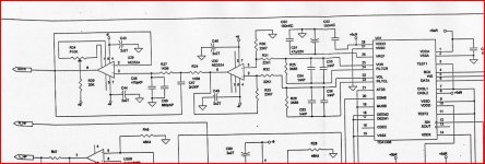
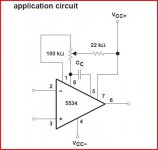
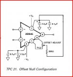
The attached picture is of the Micromega Stage 2 analogue stages and shows the pot on the final NE5534. Also shown is the 5534 and 845 offset null details as taken from the IC data sheets.
Keep the pot "as is" and initially just test and see what the DC offset is as I described earlier and see if it will adjust to zero. If it will not adjust correctly then the value of R29, that's the 20k resistor that goes to the wiper of the pot can be reduced right down to 390 or 470 ohms. Then adjust the offset again for zero.
Attachments
Hiya,
Sorry for the delay getting back to you, life's a bit manic at the moment.
I changed the op amps and the improvement was immediately obvious, much cleaner to and bottom end and a much bigger soundstage. I also bought some copper shielding which I attached to the inside-top of the case. This seemed to make the sound worse if anything, it kind of sapped the life out of everything. The ERS cloth that I bought a sheet of for £20 for an A4 size sheet was quite astounding, though. Without any exageration it seemed to unleash the hidden powers of this CD player!
So far so good! I might have a go at the caps when I get the time. As for the pots, I'm a bit lost whne it comes to building the RC filter but I shall try and learn a bit more so I can give it a go. When I'm testing to see if the output is zero do I put both the + and - of the tester on each channel seperately or do i put the + in right and the - in the left?
Thanks for your help and please excuse my ignorance once again!!
BTW I'm playing it through a pair of AR3as with a Rotel pre/power combo and a Pioneer TX7800.
Pleased you have successfully swapped the opamps OK. I found they made a significant difference to the sound quality too. Your experiments with the shielding are interesting... I would always say listen for a long time over several days whenever you do any mods as sometimes your expectations get in the way. Its appened to me many times.
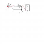
To measure the offset accurately you actually measure at the phono sockets outputs on the rear. You can measure it approximately without the filter, just have the unit in stop mode and with your meter on its most sensitive DC voltage range connect the - lead to the phono outer (which is audio ground) and the + lead to the socket inner. The reading should ideally be near zero.
The filter allows a little more precision in removing the small amount of hf noise present that can "upset" the reading on the DVM. The filter is just a resistor and cap of say 10k and 0.1uf connected in series. Not critical at all. Connect for each channel in turn and adjust the respective pot for each to give zero volts.
Attachments
Thanks for that, I'll give it a go.
I know what you mean about expectations but the ERS stuff was really quite astonishing. The seperation between the instruments in paticular was excellent and evrything seemed much tighter and more forward, without being overbearing. I alwayls loved the sound of the Micromega but at times it was a little laid back. Now it feels like it's a lot more bold but still retaining the musicality of the original.
I'm sure I'll tinker a bit more after I've settled into it. I've read that some people replace the diodes as well, what are your thoughts on this, is it worth the hassle?
Can't wait to get my Dacmagic back, will be very intruiged to see the results.
Thanks again and I'll keep you posted!
I haven't changed the diodes in the PSU. I have looked at the rails on my 100Mhz and there is no hf noise at all as the diodes come into and out of conduction.
I did replace ALL the electroylitics in mine a few years back and added 0.1uF decoupling directly across the opamp supply pins and also across the master clock oscillator (its near the SPDIF output socket). Think I mentioned this earlier on too but I also added a 68 ohm from the opamp output to the sockets to ensure absolute stability. I used surface mount parts for these and just cut the print and added them across the cut.
Certainly one of the nicest players I have heard for being musical...
Hiya,
I've fnaly got myself a DVM and have managed to check the outputs, they both read 0.1 microvolts (I think - does that sound right?) so I didn't bother to alter the pots as I figured thee reading was low enough...I did it without the cap and resistor you suggested.
What's puzzling me is that the CD player seems to be interfering with my tuner. Whenever the micromega is powered up (i.e when the screen is on rather than just when power is connected to the unit) it causes a hiss when I'm listening to the radio, it also seems to affect the sensitivity of the tuner...can't figure out why. I thought it might be a grouding issue but don't really know how to test this and there is no other hum or intefernce when listening to the player or any other source.
Think I will have a go and the caps soon...thanks for your help, I enjoy this player so much more now.
By the sounds of it you have quite a serious EMC problem, it sound like the CD player is transmiting HF noise.
If the display is connected by a ribbon cable check that everything is connected correctly. Displays and ribbon cables between display boards and main boards are quite often the prime suspects for noise, as ribbon cables are rubbish, FPCs (flying flexible cable lead into a zif socket) are used more often these days.
Try and tune in to the noise, then see how far it spreads.
Proper grounding for digital is a must, ground planes, ground planes, ground planes.
Some basics:
http://www.x2y.com/filters/TechDay0...log_Designs_Demand_GoodPCBLayouts _JohnWu.pdf
The other problem is incorrect shielding can often cause more problems than it solves, if the shielding isn't done correctly. You can create waveguides that actually increase the amount of radiated emmisions. Again not a light subject, I would sign up for this site and start reading some articvles by Keith Armstrong and Tony Waldron.
EMC Information Centre - The EMC Journal (Free in the UK)
As mooly has said, layout is everything with digital designs, SMPS etc and the ground plane is king of the design.
I've fnaly got myself a DVM and have managed to check the outputs, they both read 0.1 microvolts (I think - does that sound right?) so I didn't bother to alter the pots as I figured thee reading was low enough...I did it without the cap and resistor you suggested.
It sounds too good tbh... it wasn't in standby was it ?
Most DVM's wouldn't resolve something so low too... hmmm.When you have the top off and with the player in stop mode (not standby) measure on DC volts from ground to pin 6 of the AD845 buffer... which is the output.
What's puzzling me is that the CD player seems to be interfering with my tuner. Whenever the micromega is powered up (i.e when the screen is on rather than just when power is connected to the unit) it causes a hiss when I'm listening to the radio, it also seems to affect the sensitivity of the tuner...can't figure out why. I thought it might be a grouding issue but don't really know how to test this and there is no other hum or intefernce when listening to the player or any other source.
Think I will have a go and the caps soon...thanks for your help, I enjoy this player so much more now.
I have a vague recollection that the Micromega did interfere with FM if the tuner is nearby... I've used DAB now for a few years so it became a non problem.
Artie Allen and irishiranian,
one thing slipped my mind on this, and its important... add a cap of around 4.7pf between pin 2 and pin 6 on both the OPA604's to ensure complete stability. The exact value can be anywhere up to 10 pf... just keep both channels the same.
Sorry
one thing slipped my mind on this, and its important... add a cap of around 4.7pf between pin 2 and pin 6 on both the OPA604's to ensure complete stability. The exact value can be anywhere up to 10 pf... just keep both channels the same.
Sorry
Cool, thanks for this. | What with my tuner playing up as well, I've gt a bit of work on my hands, that and a 4 week old son, so progress is slow!
I was also wondering...I'd like to upgrade the caps too but can't seem to find any 50v 47uf caps that are in the same cylinder style as these
PANASONIC|EEUFM1H101|CAPACITOR, RADIAL, 100UF, 50V | Farnell United Kingdom
I can only find this
PANASONIC|EEEFC1H470P|CAPACITOR, CASE G, 47UF, 50V | Farnell United Kingdom
can they be used as a replacement for a more traditional cylinder cap that is in the player at the moment?
I'm a bit wary about changing the ones under the drive mech as I know they can be teprimental, I was just going to stick to the analogue phase, what do you think?
(BTW, I still really rate the difference the ERS stuff made, wondered if anyone else had any experience of it.)
Nice one and thanks for your time.
Christian
Try these (the pictures are just a standard image, not 16 volt ones),
RUBYCON|50YXM47MEFC6.3X11|CAPACITOR, 47UF, 50V | Farnell United Kingdom
Plenty to choose from,
Your Search Results | Farnell United Kingdom
CPC (part of Farnell) keep doing free web delivery on orders over £10) just keep checking the website and follow the instructions carefully.
Your Search Results | CPC
The 4.7pf caps for the opamp. (These are 10pF but still OK) Good quality foil type)
LCR COMPONENTS|FSC 160V 10PF+/-1PF|CAPACITOR, 160V 10PF | CPC
or,
VISHAY BC COMPONENTS|D479C20C0HF63L2R|CAPACITOR, DISC, 100V, 4.7PF | Farnell United Kingdom
- Home
- Source & Line
- Digital Line Level
- Micromega Stage 2 modification - and incorrect info...