Hi Mooly, Thanks for the reply. How many OPA604AP and AD845JNZ do i need and what is an I/C and why is it "hard" to remove (Sorry for my ignorance). What are electroylitics and how do i replace those. Would it be possible too send me a diagram of the work you carried out and the steps it took.
Appreciate it !! All the best, Simon.
Appreciate it !! All the best, Simon.
The best thing is for you to remove the cover and look ")
It's so easy to dismantle... really is two minutes to remove the PCB.
Get two paperback books, stand the player on it's front with a book each end so as not to damage the switches etc, and then remove the 6 Torx screws holding the case. The case then just slides off.
With the top off look at the large circuit board near the sockets and there are 4 opamps of the NE5534 type. These are the 8 legged IC's. They are what have to be removed.
If you want to remove the PCB first look at the ribbon cable plug and sockets. They just plug in. Look at the ends of the plugs where there are tiny plastic "wings" that help it fit securely. Try not to break them, but it doesn't matter if you do and just gently lever them away a tiny fraction while gently pulling on the ribbon to release. Keep trying one end, then the other, dont rip it out in one go at an angle as that risks bending the connectors. All common sense stuff.
Undo the two ? I think screws securing the phono sockets to the rear panel.
Now gently unclip each support on the PCB. They just push on and off but have a springy plastic "catch"... obvious when you look. Just work each one carefully and remove the whole PCB as one.
Honestly, it takes under a minute to do all that
The big question then is if you feel able to remove those I/C's. The only realistic way without special gear is to first cut each leg as close to the body of the IC as possible.
Now I was thinking about this... although I would then go on to remove the left over wire and clear each hole... you dont have too. You could tidy all the stubs up, then solder the new IC on the top. The holes are plated through you see, that's what makes removing difficult, or rather getting the old solder out of the hole.
See what you think and feel about it first when you perhaps have had a look.
Fitting new IC's on top should be relatively easy and "safe"... the last thing you want to do is damage the fine print on the board.
It's so easy to dismantle... really is two minutes to remove the PCB.
Get two paperback books, stand the player on it's front with a book each end so as not to damage the switches etc, and then remove the 6 Torx screws holding the case. The case then just slides off.
With the top off look at the large circuit board near the sockets and there are 4 opamps of the NE5534 type. These are the 8 legged IC's. They are what have to be removed.
If you want to remove the PCB first look at the ribbon cable plug and sockets. They just plug in. Look at the ends of the plugs where there are tiny plastic "wings" that help it fit securely. Try not to break them, but it doesn't matter if you do
and just gently lever them away a tiny fraction while gently pulling on the ribbon to release. Keep trying one end, then the other, dont rip it out in one go at an angle as that risks bending the connectors. All common sense stuff.Undo the two ? I think screws securing the phono sockets to the rear panel.
Now gently unclip each support on the PCB. They just push on and off but have a springy plastic "catch"... obvious when you look. Just work each one carefully and remove the whole PCB as one.
Honestly, it takes under a minute to do all that
The big question then is if you feel able to remove those I/C's. The only realistic way without special gear is to first cut each leg as close to the body of the IC as possible.
Now I was thinking about this... although I would then go on to remove the left over wire and clear each hole... you dont have too. You could tidy all the stubs up, then solder the new IC on the top. The holes are plated through you see, that's what makes removing difficult, or rather getting the old solder out of the hole.
See what you think and feel about it first when you perhaps have had a look.
Fitting new IC's on top should be relatively easy and "safe"... the last thing you want to do is damage the fine print on the board.
Mooley, I need to order the stuff from Farnell's. Am i right in thinking i need 2 OPA604's and 2 AD845's. I have a mate who has an iron, solder, cutters etc and he is willing to help. Is there anything else i need, in one post you mention a 68 ohm resistor ?
Appreciate your time and have a good weekend.
Simon.
Appreciate your time and have a good weekend.
Simon.
Yes, I used two OPA604's and two AD845's in mine and am very pleased with the result, however you may want to use sockets and experiment with different types though...
When I was trying different ones I found even TL071's were a noticeable improvement sonically.
The 68 ohms are fitted in series with the audio output (you cut the print with a sharp craft knife) and solder the resistor across the cut. It's probably unneccessary to do that in practice for this application... it's to prevent any possiblity of HF instability if a cable (interconnect) with high capacitance was used, however as it's something that's recommended by the manufacturer of the AD845, it's silly not to observe the precaution.
If you order IC's make sure you get the DIP package and not the tiny surface mount types.
TEXAS INSTRUMENTS|OPA604AP|OP AMP, VFB FET I/P, 8PDIP | Farnell United Kingdom
ANALOG DEVICES|AD845JNZ|OP AMP, FET FAST SETTLING, DIP | Farnell United Kingdom
As for resistors... you might be better just getting two from Maplin if you have a store locally The value isn't critical at all, 56, 68, 82 ohms, all would be fine.
Farnell do them but you have to buy in large multiples. If you haven't a Maplins I'm sure we can find a suitable one from Farnell without having to order 50 of them
Capacitors for decoupling, you need two packs of 5,
VISHAY BC COMPONENTS|225232508104|CAPACITOR, 0.1UF, 50V | Farnell United Kingdom
Solder braid for cleaning up the excess solder when removing the old IC's... you asked... IC is Integrated Circuit. Thats all those black packages with lots of legs
http://uk.farnell.com/arexx/aw-100/desoldering-braid-esd-safe-2mx2/dp/1661554
Haven't used one of these in years but at the price might be worth getting,
http://uk.farnell.com/duratool/8pk-...ssellid=3125634&crosssell=true&in_merch=true&
When I was trying different ones I found even TL071's were a noticeable improvement sonically.
The 68 ohms are fitted in series with the audio output (you cut the print with a sharp craft knife) and solder the resistor across the cut. It's probably unneccessary to do that in practice for this application... it's to prevent any possiblity of HF instability if a cable (interconnect) with high capacitance was used, however as it's something that's recommended by the manufacturer of the AD845, it's silly not to observe the precaution.
If you order IC's make sure you get the DIP package and not the tiny surface mount types.
TEXAS INSTRUMENTS|OPA604AP|OP AMP, VFB FET I/P, 8PDIP | Farnell United Kingdom
ANALOG DEVICES|AD845JNZ|OP AMP, FET FAST SETTLING, DIP | Farnell United Kingdom
As for resistors... you might be better just getting two from Maplin if you have a store locally
The value isn't critical at all, 56, 68, 82 ohms, all would be fine.Farnell do them but you have to buy in large multiples. If you haven't a Maplins I'm sure we can find a suitable one from Farnell without having to order 50 of them
Capacitors for decoupling, you need two packs of 5,
VISHAY BC COMPONENTS|225232508104|CAPACITOR, 0.1UF, 50V | Farnell United Kingdom
Solder braid for cleaning up the excess solder when removing the old IC's... you asked... IC is Integrated Circuit. Thats all those black packages with lots of legs
http://uk.farnell.com/arexx/aw-100/desoldering-braid-esd-safe-2mx2/dp/1661554
Haven't used one of these in years but at the price might be worth getting,
http://uk.farnell.com/duratool/8pk-...ssellid=3125634&crosssell=true&in_merch=true&
Last edited:
Still not triggering I'll unsubscribe from the thread and resubsribe and see what that does.
Found Angelique Kidjo on Utube... it's not really my thing tbh but can see the appeal of it.
Now this
YouTube - Beethoven: String Quartet No. 14 - Takacs Quartet
on CD is fantastic (through the Stage 2 of course)
I'll unsubscribe from the thread and resubsribe and see what that does.Found Angelique Kidjo on Utube... it's not really my thing
tbh but can see the appeal of it.Now this
YouTube - Beethoven: String Quartet No. 14 - Takacs Quartet
on CD is fantastic (through the Stage 2 of course)
Work slowly, remove the cover and PCB as previously mentioned, then replace cover to stop any damage to player... make sure you note (take a picture) which way round the four NE5534's are located before you remove any.
You have to decide "how" you want to remove them. Just do one at once. They are going to have to be cut out one leg at a time. The cut is made as close to the body of the IC as possible, which will leave 99% of the old legs still in place.
You then support the board vertically, and while heating with soldering iron the first pin from underneath. At the same time using tweezers etc pull the old leg out from above.
It's very important not to damage the print on the PCB... some of it is very fine.
I would really recommend you to try this on some scrap item first such as an old remote etc.
You mustn't "poke" the board with the iron as that will damage the print.
Hmmm... OK now I'm puzzled. The Stage 2 (as far as I know) just used NE5534's.
Did you buy it new ? or has it been modified before ? If you look at the underside of the PCB you will soon tell if the soldering is original or not.
Is it the two IC's nearest the output sockets, or the two nearer the middle of the PCB. There is actually another opamp on the PCB that's used just as a headphone amp, a 4560 from memory.
Can you post a picture maybe on here...
The LT1227 is an odd choice of device... it's a current feedback opamp.
Edit... the notifier worked
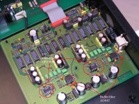
This isn't my player by the way, but this shows the vital parts. I have added the text.
All four opamps "should" be 5534's as far as I know from new.
The IV convertors I swapped for the OPA604 and the buffers for the AD845.
Notice the multiturn trimpots are missing... those 3 empty solder pads. I take it they are fitted to yours.
In the top left is the headphone amp opamp.
All four opamps "should" be 5534's as far as I know from new.
The IV convertors I swapped for the OPA604 and the buffers for the AD845.
Notice the multiturn trimpots are missing... those 3 empty solder pads. I take it they are fitted to yours.
In the top left is the headphone amp opamp.
Attachments

What's the date on Thursday !!
So you have 12 hours to fix it
Does your PCB look like the one in the picture ?
- Home
- Source & Line
- Digital Line Level
- Micromega Stage 2 modification - and incorrect info...